0 Preface
Visibility, that is, the visible distance of the target, refers to the maximum distance that can be distinguished from the background when the target is observed. In recent years, due to various reasons, the visibility of the atmosphere in the world is getting lower and lower, the greenhouse effect is becoming more and more obvious, and smog and dust storms have become hot topics. The production of national defense industry and the daily life of the people have been greatly affected. Strengthening the measurement of CO2 and visibility in the air is imminent.
At present, the visibility instruments that have been developed in the world have two types of transmission and scattering, and the research on visibility measuring instruments in China is not yet mature.
This paper presents a simple design of a transmissive visibility measuring device with CO2 detection. Using single-chip control, the measurement and display are integrated, the instrument is simple and practical, and the measurement results are clear at a glance. The volume is small and easy to carry, the data is real-time and the flexibility is large. The experiment verified that the program basically meets the needs of daily life.
1 Measuring device principle and structure block diagram
The device includes a visibility measurement system and a CO2 measurement system, as shown in Figure 1.
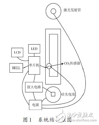
The attenuation of light is caused by the scattering and absorption of particles along the beam path. In the visibility measurement system, the laser emitting tube emits laser light, and the silicon photocell detects the light transmittance of the horizontal air column in the sampling space, and the optical signal is converted into a voltage signal. At this time, the change of voltage reflects the change of visibility. The device controls a plurality of LED lights through a single-chip microcomputer to directly reflect the visibility of the measured environment. In the CO2 measurement system, the CO2 sensor uses MG811, which uses the principle of solid electrolyte battery to sample the potential difference (EMF) between the sensor's sensitive electrode and the reference electrode. The potential difference is amplified and temperature compensated into the microcontroller, and the formula is corrected and converted to CO2 concentration. And through the LCD screen display, use a buzzer to alarm the high concentration of CO2 conditions.
2 hardware and software design
2.1 Hardware Design
The hardware circuit of the device can be divided into three parts: a signal acquisition circuit, a control circuit and a display circuit. The main functional block diagram of the device is shown in FIG. 2 .
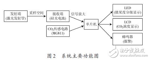
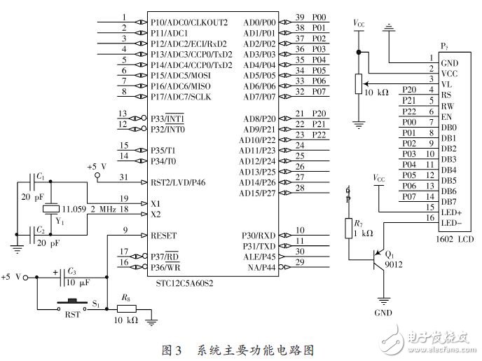
The signal acquisition circuit includes a laser emitting end, a photosensitive receiving end and a CO2 sensing circuit for collecting the signal to be tested. The control circuit is a signal amplifying circuit and a data control processing unit for analyzing and processing the sampled data. The display circuit includes visibility display circuit, CO2 concentration display and alarm circuit, and real-time output results, which directly reflect the visibility and CO2 concentration of the current environment. The main function circuit diagram of the system is shown in Figure 3.
This series high power density programmable dc electronic load provides three voltage ranges 200V DC Electronic Load/600V DC electronic load /1200V DC Electronic Load. Supports CV, CC, CR and CP these 4 basic operating modes, as well as CV+CC, CV+CR, CR+CC these 3 complex operating modes. Full protection includings OCP, OPP, OTP, over voltage and reverse alarm. Support external control and monitor mode, the 0 to 10V input or output signal represent 0 to full range voltage or current. Provide OCP test, OPP test and Short circuit simulation to effectively solve the application demands for power and automated testing. Built-in RS232, RS485 and USB communication interfaces, LAN&GPIB communication card is optional. Two or more loads can be connected in master-slave parallel mode to provide more power or current capacity,which can make DC Electronic Load System in 200V DC Electronic Load System,600V DC electronic load System,1200V DC Electronic Load System . This series DC load can be applied to battery discharge, DC charging station and power electronics and other electronics products.
Speical features as below:
â— Flippable front panel and color touch screen allow convenient access and operation
â— Provides four kinds of basic working mode such as CV/CC/CR/CP, and CV+CC/CV+CR/CR+CC complex operating modes
â— Adjustable current slew rate, adjustable CV loop speed
â— Ultra high precision voltage & current measurement
â— OCP/OPP testing function
â— 50kHz high-speed CC/CR dynamic mode
â— 500kHz high-speed voltage and current sampling rate
â— Timing & discharging measurement for batteries
â— Short circuit test mode
â— Auto mode function provides an easy way to do complicated test
â— Dynamic frequency sweep function for determining worst case voltage peaks*
â— Non linear load mode function makes the simulated loading current more realistic*
â— Supports external analog control function*
â— V-monitor/I-monitor
â— LED load simulation function
â— Full protection: OCP, OPP, OTP, over voltage and reverse alarm
â— Up to 20 units master/slave parallel control
â— Front panel USB interface supports data import and export
â— SCPI language and standard rack size make it ideal for ATE System integration
â— Smart fan control with lower noise and better for environment
â— Multi versions to meet the cost performance and different applications
* Only professional Electronic Load units support these functions
DC Electronic Load
DC electronic load,electronic load,DC load,ac electronic load, electronic load
APM Technologies (Dongguan) Co., Ltd , https://www.apmpowersupply.com