1 Introduction
In the design of digital integrated circuits, after the design engineer completes the design in the hardware description language (HDL: Hardware DescripTIon Language), it is necessary to verify whether the design satisfies the expected function through simulation. In the simulation, the design engineer needs to establish a test platform for the design project. This test platform provides the most complete test stimulus for the design project and provides an output response that can be observed. Based on these output response information, the design engineer can judge Whether the design project meets the expected functionality. When performing simulation projects, the design engineers generally perform simulation verification on each functional module, and then simulate the entire system design after passing through. When a design engineer finds an error in the simulation, it needs to be carefully debugged to find out the cause of the error and modify it.
As the complexity of system design increases, when the design integration exceeds one million gates, the verification of design correctness is more difficult than the design itself, and the real-time performance of the system simulation is difficult to meet the requirements. When software simulation is performed on complex circuits, the simulation time of the system often needs to occupy most of the design time. We often have to wait a few hours or even days to simulate certain functions of the circuit. How to improve simulation efficiency, reduce simulation complexity, and shorten simulation time will become a key part of system design. Using C-based design and verification methods to replace traditional HDL-based design simulations, thus speeding up simulation, but This method is only applicable to the early stages of design. In order to realize the simulation verification conveniently and quickly, and get the test data in time, this paper proposes the idea of ​​using hardware acceleration, and uses the hardware simulation platform and the software simulation platform to communicate with each other, that is, through the combination of the simulation software running on the host and the hardware platform to realize the software and hardware. Synchronous acceleration simulation can increase simulation speed by 30 times.
2 software and hardware collaborative acceleration simulation
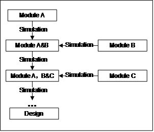
In the traditional design and verification process, the design engineer first expresses the complex system module by module in the hardware description language. After all modules are verified separately on the simulator, the simulation of the local and the whole design is performed through the integration between modules, such as Figure 1 shows.

Figure 1 Design verification process
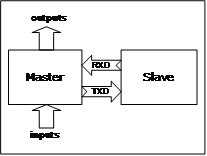
Assume that the module Master and the module Slave are part of the overall complex design. The module master is responsible for data processing of the input data, and then sends the processed data to the next module Slave. The Slave module completes a complex algorithm operation. After the operation ends, the result is returned to the module master, and the next step is performed. as shown in picture 2.

Figure 2 design example block diagram
After completing the HDL design of the module Master and the module Slave, the design engineer used the HDL simulator software to verify the two modules separately. The simulation time of the module master took five minutes, and the module Slave took fifteen minutes. Two modules were used. Co-simulation took twenty minutes. If the design is not correct, the design will be re-modified and simulated until the verification passes, and the repeated simulation work will take days or even weeks. In order to shorten the simulation time, this paper proposes to use hardware acceleration to simulate the software and hardware collaborative acceleration simulation. The functions of the module Master and the module Slave are first simulated and verified on the software. After the Slave module is integrated, the module Slave is downloaded to the hardware. The module master is still running on the software and is implemented by the external interface provided by the HDL simulation tool. The data interaction between the hardware, the joint simulation of the module Slave and the module master, once the simulation passes, the module master and the module Slave are put into the hardware for accelerated simulation verification, then the joint simulation time of the two modules will be greatly shortened.

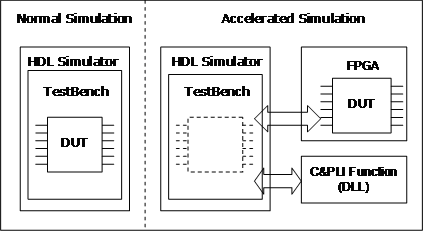
Figure 3 accelerated simulation
The block diagram of the accelerated simulation technology described in this paper is shown in Figure 3. DUT (Design Under Test) is designed by the synthesizable Verilog HDL language. After the DUT is integrated, it is downloaded to the Field Programmable Gate Array (FPGA) for accelerated simulation verification. The test file TestBench running on the HDL simulator sends the test stimulus to the DUT and responds to the output information. The information exchange between the FPGA and the HDL simulator is implemented by the Verilog Programming Language Interface (PLI) provided by the simulator. Verilog PLI provides a mechanism for Verilog code to call functions written in C language. It provides an interface between C language dynamic linker and emulator, which can realize co-simulation of C language and Verilog language. Since the C language has advantages over the Verilog language in process control, the C program can be used to generate values ​​for testing the stimulus and reading the signal. Taking the Windows platform as an example, the user compiles the code and generates a dynamic link library (DLL: Dynamic Link Library) by using C language and Verilog PLI, and then calls these functions in TestBench written by Verilog. When the TestBench file is executed for simulation, once the C function in TestBench is successfully linked, the C function passes the detailed information to the HDL simulator, and the C function can be simulated like the simulated Verilog code. In this way, the design engineer can use the Verilog PLI interface to create his own system call tasks and system functions, and then can perform auxiliary simulation on the DUT through C language programming, which can not achieve the functions that Verilog syntax can not achieve.
1, The Wall-Mounted Infrared Thermometer AT100 accurately measures a person`s body temperature in 1 second. A reading distance is 1-10cm, equipped with a clear LCD Digital Display.
2, Switching Between ℃ and ℉
3, AT100 infrared forehead thermometer, no need to hold Wall Mounted Installation
4, Infrared technology, 45s no operation, enters the standby mode; wake up when people approach
5, Fever Beeper
6, For Offices Shops Schools
Smart Infrared Thermometer,Infrared Thermometer No Touch,Wall-Mounted Non-Contact Digital Temperature Thermometer
Axiswell Technology Co., Ltd , https://www.medhealthycare.com