1 Overview
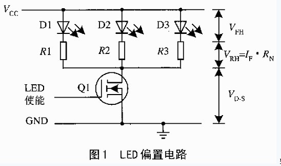
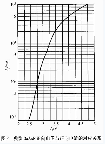
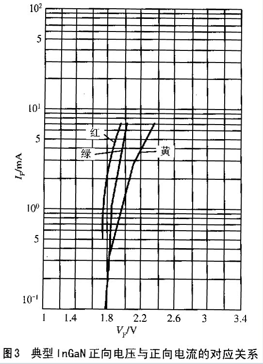
The LED is a current driven device and the light output intensity is determined by the current flowing through the diode. Figure 1 is a simple bias circuit composed of a voltage source and a current limiting resistor. The current flowing through the LED is determined by the following equation: IDIODE = (VCC - VF) / [RLIM + RDS (ON)] Low, but different diode VF (forward voltage) parameters are consistent. Figure 2 and Figure 3 show the forward voltage (typical) of the LED at 25 °C versus the on current. It can be seen from the current index that for GaAsP diodes, VF can rise to 2.7V (+40%); for InGaN diodes, VF can be programmed up to 4.2V (+20%). If multiple LEDs are required in the system, such as a cellular phone backplane display using 8 LEDs, the design according to Figure 1 will require multiple current limiting resistors, occupying a larger circuit board area.
If Vcc is increased to more than 10 times VF, the effect of VF variation can be reduced, but the power consumption is large and does not meet the requirements of battery-powered products. For systems powered by a single Li+ battery, the Li+ battery voltage varies from 4.2 to 3V. If the LED's bias circuit is simply provided by a Li+ battery and a current limiting resistor, the output brightness will vary significantly. A reasonable solution should be to use a current bias circuit.
2 current bias circuit
   The current bias circuit actually uses a current source to bias the LEDs. If the current source has sufficient dynamic range, this biasing will not be affected by VF variations. Figure 4 is a block diagram of the current biasing scheme. This circuit replaces the current limiting resistor in Figure 1 with a current source. The light output intensity is independent of the Power Supply and forward voltage, as long as there is enough supply voltage to bias the current source and LED. In Figure 4, Q1 is the enable control switch. A dedicated LED driver chip such as the MAX1916 provides an advanced LED current bias circuit. The MAX1916 integrates three sets of current sources in a tiny SOT23 package, and the current flowing through RSET is mirrored to three outputs, as shown in Figure 5. Several identical MOSFETs in the circuit have phase-to-source power supplies, so their channel currents are the same and the magnitude of the current is determined by the mirror current ISET. The maximum current mismatch of the MAX1916 is %26; #177; 5%, and the "mirror coefficient" is 200A/A. That is, when ISET is 50 μA, the current at each output is 10 (1% 26; #177; 0.05) mA (maximum). The SET terminal is internally biased at 1.25V. ISET is determined by the following equation: ISET = (Vcc - 1.25V) / RSET IOUT = 200ISET, the deviation between each current is % 26; #177; 5%. Output saturation voltage:
~ 
VOUT(SAT)=RD-S%26;#183;IOUT The drain-source resistance of MAX1916 is guaranteed to be no higher than 50Ω over the entire temperature range. The minimum voltage required for a GaAsP diode operating at 2mA to ensure normal operation is: VF +100mV, 2.71V input voltage can protect the GaAsP LED operating voltage to 2.7V. In order to obtain a lower differential voltage and higher output current, the three outputs of the MAX1916 can be connected in parallel to form a current source with a "mirror coefficient" of 600. As shown in Figure 6, the drain-source resistance after paralleling is 50/3 = 16.67 Ω (maximum). This connection allows a single white LED to reach 20mA or more at 3V supply, meeting the backlight requirements of current portable cellular phones and other products. The voltage source used to set the terminal current can be provided separately from the main power source with strong carrying capacity. For example, in a cellular phone, the VSET can be provided by a low noise +2.8V power supply of a radio frequency (RF) circuit. If powered directly from a single-cell Li+ battery, the MAX1916 is suitable for driving GaAsP LEDs with lower forward voltages, while other InGaN white LEDs with higher forward voltages require additional drive schemes. Because the Li+ battery is powered, the input voltage may not meet the bias voltage required by the LED as the battery discharges.