With the rapid development of integrated circuit technology, new remote control based on various types of chips has emerged. The central control unit of the remote control device has been gradually developed from the early discrete components and integrated circuits to the current single-chip microcomputer, and the degree of intelligence is greatly improved.
In the field of wireless remote control, the currently used remote control methods mainly include ultrasonic remote control, infrared remote control, and radio remote control. Because the technical characteristics of radio waves can be realized in a large area and space, it becomes the main mode of remote control, and has wide application value in production, construction and daily life.
Therefore, based on the previous research, a design method of programmable radio remote control multi-channel switch system based on single-chip microcomputer control technology is explored. The research shows that the remote control switch system designed by this method is convenient to control and is suitable for occasions with more controlled appliances, which can realize multi-channel multi-function control.
2 system design
2.1 System Analysis
The system structure mainly consists of an antenna receiving part, a signal transmitting part, a single chip control part and a driving part. Since radio signals are easily interfered by environmental factors, it is difficult to make a success without professional equipment. Wireless data transmission and cable are different. The transmitted data is stable only for a short period of time. If the time is long, it will be interfered. Therefore, the data must be transmitted when the data is transmitted. In the design, the high frequency part is selected for special use. The transmitting and receiving modules, while the data encoding and decoding are also completed by hardware, thus greatly improving the success rate of the production; the control part is the core of the system, in order to enhance the system's scalability and flexibility, and make the circuit simple and clear, Save hardware design costs and introduce mature microcontroller control technology into system control. The specific composition of the system is shown in Figure 1.
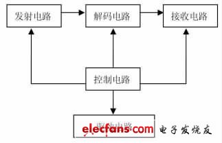
Figure 1 System block diagram
2.2 System main circuit
2.2.1 Transmitting system circuit
The transmitting system is mainly composed of a key addressing circuit, an encoding circuit, and a remote control transmitting circuit. The main component of the key addressing circuit is the priority encoder CD74HC147.CD74HC147 has nine inputs, four outputs, the input and output are active low, and the code has a priority limit, that is, when there is greater than or equal to At the 2 input, only the input with the highest priority is valid; the main component of the completion coding circuit is PT2262, which is a low-power low-cost general-purpose coding circuit based on CMOS technology, with 12-bit tri-state address. Terminal pin, any combination can provide 531,441 kinds of address codes, up to 6 data terminal pins, set address code and data code serial output from l7 pin for wireless remote control transmitting circuit; remote control transmitting circuit adopts 315MHz The wireless transmitter module has three pins: the power positive pin, the ground pin, and the serial signal input pin. This module has a wide operating voltage range of 3V~12V, so the transmitting frequency is basically unchanged when the voltage changes, and the receiving module matched with the transmitting module can receive stably without any adjustment. The module is characterized by relatively large transmission power and long transmission distance, which is suitable for communication under severe conditions.
The schematic diagram of the transmitting system circuit is shown in Figure 2.
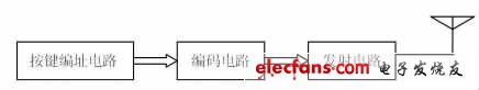
Figure 2 Schematic diagram of the transmission system circuit
The insulated terminal is actually a piece of metal sealed inside the insulating plastic. There are holes at both ends to insert the wire. There are screws for fastening or loosening. For example, two wires, sometimes need to be connected, sometimes need to be disconnected. They can be connected by terminals and can be disconnected at any time without having to solder or entangle them, which is convenient and quick. And very beautiful, the cabinet does not look so messy, with an orderly wiring.
classification
Round pre-insulated terminal, cold-pressed terminal block, electric power fitting, fork-shaped pre-insulated terminal, pin-shaped pre-insulated terminal, chip-shaped pre-insulated terminal, bullet-shaped fully insulated terminal, elongated intermediate joint, short intermediate joint, round Bare end, fork-shaped bare end, male and female pre-insulated terminal, tubular pre-insulated terminal, tubular bare end, pin-shaped bare end, peephole series SC, DTG copper terminal, C45 special terminal range insulated terminal Also known as cold-pressed terminals, electronic connectors, air connectors are attributed to cold-pressed terminals.

Insulated Terminal Connector,Ring Terminals,Heat Shrinkable Butt Connectors,Shrinkable Fork Terminals
Ningbo Bond Industrial Electric Co., Ltd. , https://www.bondelectro.com