0 Preface
With the continuous development of mobile communication technology, users have put forward higher requirements for the content and quality of mobile communication. In order to adapt to the trend of global wireless communication, such as mobilization, broadband and IP, and to compete with some emerging mobile communication technologies such as WiMAX and Wi-Fi, at the end of 2004, 3GPP proposed following HSDPA, HSUPA and other technical standards. 3G Long Term Evolution (3G LTE). The goal of 3G LTE is to achieve higher data rates, lower latency, improved system capacity and coverage, and lower cost. At the same time, since LTE adopts an orthogonal frequency division multiple access (OFDMA) access mode, information of users in a cell is carried on different carriers that are orthogonal to each other, so interference comes from other cells. That is, interference between cells. Therefore, interference suppression between cells has become an urgent problem to be solved. This paper introduces the main interference suppression methods currently used in LTE, and compares the advantages and disadvantages of different methods.
1 Introduction to LTE
LTE fills the huge technological gap between third-generation mobile communications and fourth-generation mobile communications. The goal is to build an evolving wireless access architecture that can achieve high transmission rates, low latency, and packet-optimized. The LTE system expects to achieve a downlink transmission rate of 100 Mbit/s over a bandwidth of 20 MHz, an uplink transmission rate of 50 Mbit/s, and a spectrum efficiency of 2 to 4 times that of HSPA. Support enhanced multimedia broadcast multicast service and packet switching of all packets, flexible bandwidth configuration, significantly improved transmission rate of edge cells, and enhanced system coverage. In order to achieve the above objectives, the LTE system adopts a flat network structure that is close to a typical all-IP broadband network, and adopts multiple input multiple output (MIMO), orthogonal frequency division multiplexing (OFDM), and hybrid automatic request weight. Advanced technologies such as HARQ and adaptive modulation coding (HARQ). The uplink of the LTE system adopts a single carrier frequency division multiple access (SC-FDMA) access method based on the OFDM transmission technology. The downlink adopts the access mode of OFDMA. The access mode of 0FDMA is different from that of code division multiple access (CDMA), and it is impossible to eliminate inter-cell interference by spreading. The LTE system has high requirements on spectrum efficiency, and cannot pass the traditional method of using higher multiplexing coefficients. The frequency reuse method is used to attenuate interference. Therefore, in LTE, attention is paid to interference suppression technology between cells. At present, the main ways of suppressing inter-cell interference discussed by 3GPP are divided into three types, namely, inter-cell interference randomization, inter-cell interference deletion, and inter-cell interference coordination/avoidance.
2 small interval interference suppression technology
The OFDM-specific OFDMA access mode enables user information in the own cell to be carried on different carriers that are orthogonal to each other, so all interference comes from other cells. For users in the community center. The distance from the base station is relatively close, and the interference signal distance of the outer cell is far away, so the signal to interference and noise ratio is relatively large: but for the user at the cell edge, because the neighboring cell occupies the same carrier resource, the user The interference is relatively large, and the distance from the base station is relatively small, and the signal-to-noise ratio is relatively small, resulting in poor service quality of the cell edge. Low throughput. Therefore, in LTE, the inter-cell interference suppression technique is very important.
2.1 Interference randomization
For the access mode of 0FDMA, the number of interference from the outer cell is limited, but the interference intensity is large, the interference source is also changed quickly, and it is difficult to estimate. Therefore, using mathematical statistics to estimate the interference becomes a relatively simple and feasible method. Methods. Interference randomization cannot reduce the energy of interference, but it can be randomized into "white noise" by means of scrambling the interference signal, thereby suppressing inter-cell interference, so it is also called "interference whitening". The methods of interference randomization mainly include cell-specific scrambling and cell-specific interleaving.
a) Cell-specific scrambling, that is, after channel coding, the interference signal is randomly scrambled. As shown in FIG. 1, for cell A and cell B, after channel coding and interleaving, the transmission signals are respectively scrambled. If there is no scrambling, the decoder of the user equipment (UE) cannot distinguish whether the received signal is from the local cell or from other cells, and it may decode the signal of the local cell or decode the signals of other cells, so that the performance is performed. reduce. The cell-specific scrambling can distinguish the information of different cells by different scrambling codes, so that the UE can only decode the useful information to reduce interference. Scrambling does not affect bandwidth, but it can improve performance.
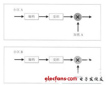
Figure 1 cell exclusive scrambling
b) Cell-specific interleaving, that is, after channel coding, the transmission signals are interleaved in different ways. As shown in FIG. 2, for cell A and cell B, the interference signals are respectively interleaved after channel coding. The cell-specific interleaving mode can be generated by a pseudo-random number method. The number of available interleaving patterns (interleaving seed) is determined by the interleaving length. Different interleaving lengths correspond to different interleaving pattern numbers, and the UE end determines the number of interleaving patterns. Which interleaving mode is used. Interleaved seeds can be multiplexed between cells that are far apart in space, similar to frequency division multiplexing in cellular systems. For randomization of interference, cell-specific interleaving and cell-specific scrambling can achieve the same system performance.
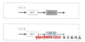
Figure 2 cell exclusive interlacing
2.2 interference removal
The idea of ​​interference cancellation was originally proposed in the CDMA system. The signal of the interfering cell can be demodulated and decoded, and then the interference from the cell is reconstructed and deleted. Although LTE adopts the 0FDMA access method, the concept of interference deletion is still introduced. There are two main methods for implementing the small-area interference deletion.
a) The interference cancellation is performed by the multi-antenna space suppression method at the receiving end. The related detection algorithm has been widely used in the research of multiple input and multiple output (M1 - MO).
b) Based on the method of checking N/Delete. Typically, if inter-cell interference is removed by using interleaved multiple access (IDMA), the IDMA can generate different interleaving patterns through a pseudo-random interleaver and allocate them to different cells. The receiver deinterleaves with different interleaving patterns to achieve the target. The signal and the interference signal are respectively solved, and then the interference signal is subtracted from the total received signal, thereby effectively improving the information of the received signal and the comparison noise ratio.
In addition, in the downlink transmission of LTE. The information of the interference signal can be obtained in different ways. When the inter-Node B interference is deleted, the interference signal information can be obtained by detecting the interference control signal of the UE side; when the inter-sector interference is deleted, the Node B directly uses the control channel of its own to send the interference signal information to the UE. Obviously, the more interference signal information the receiver acquires, the better the performance of interference cancellation.
The advantage of the small interval interference deletion is that there is no limitation on the frequency resources at the cell edge, and the neighboring cells can use the same frequency resource even at the cell edge, and can obtain higher cell edge spectrum efficiency and total spectrum efficiency. The limitation is that the cells must be kept in synchronization, and the target cell must know the pilot structure of the interfering cell to perform channel estimation on the interference signal. For users who want to perform inter-cell interference deletion, they must be assigned the same frequency resource.
2.3 Interference coordination / avoidance
For the 0FDMA access method. The user in the cell center is neither disturbed by the users of the cell. The interference source from the outer cell is far away, so a better reception effect can be achieved. The interference from the external cell to the user at the edge of the cell is more serious.
The core idea of ​​interference coordination is to restrict the available resources of a cell by inter-cell coordination to reduce the interference of the cell to neighboring cells, improve the signal-to-noise ratio of neighboring cells on these resources, and the cell edge. Data rate and coverage. The industry has proposed a number of methods for interference coordination/avoidance. This paper will introduce a generally accepted soft frequency reuse scheme.
In this scheme, the subcarriers in each cell are divided into two groups. One group is called the primary subcarrier and the other is called the secondary subcarrier. The primary subcarriers can be used across all cell ranges, while the secondary subcarriers can only be used in the central region of the cell (see Figure 3). In this way, the subcarriers can be allocated in such a way that the subcarriers used in the neighboring cell boundaries are homogeneous.
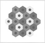
Figure 3 Schematic diagram of soft frequency reuse
Mutual orthogonal, users using the same frequency subcarriers are far enough apart. Thereby, the co-channel interference of users at the edge of the neighboring cell is effectively avoided or reduced. For users in the cell center. Because it is closer to the base station itself. Moreover, the interference received by the outer cell is small, so the transmission can be performed with a relatively low power, and the opposite is true for the user at the cell edge. Therefore, in general, the maximum transmit power allowed by the primary subcarrier is higher than the maximum transmit power allowed by the secondary subcarrier. With a certain power spectral density, more power is allocated to the primary subcarriers, meaning that the primary subcarriers are allocated a wider bandwidth. The transmit power ratio of the secondary subcarrier to the primary subcarrier can be adjusted between 0 and 1, and the corresponding effective frequency reuse coefficient varies from 3 to 1. By adjusting the power ratio of the secondary subcarrier and the primary subcarrier, the soft frequency multiplexing can adapt to the traffic distribution change of each cell. When high traffic occurs at the cell edge, the power ratio is set to a relatively small value to obtain a higher cell edge throughput; conversely, when the traffic is mainly concentrated inside the cell. A larger power ratio can be set.
2.4 Comparison of several interference suppression techniques
Comparing the several schemes for interference suppression of the LTE system introduced above, it can be seen that the interference randomization continues to use the mature scrambling technology of the CDMA system, which is relatively simple and feasible. However, the problem is to treat interference as white noise processing, which may cause measurement errors due to different statistical characteristics. Interference cancellation technology can significantly improve system performance at the cell edge and obtain higher spectrum efficiency, but it is not suitable for services with smaller bandwidth (such as VolP), and it is more complicated to implement in OFDMA system. There are not many studies on it in the follow-up. Interference coordination/avoidance is a hot technology in current research, and its implementation is simple and can be applied to services of various bandwidths. And it has a good effect on interference suppression, and is suitable for the specific access mode of OFDMA, but brings about the loss of the overall throughput of the cell while improving the performance of the cell edge user. The interference suppression methods between the above three types of cells can be combined with each other to complement each other to obtain higher system gain.
3 Conclusion
The LTE system has high requirements for spectrum efficiency. The resulting inter-cell interference problem is an important issue affecting system performance. Interference randomization, interference cancellation and interference coordination/avoidance as effective inter-cell interference suppression techniques will greatly improve the performance of 3G LTE systems, especially to improve the performance of cell edge users.
The main control unit of the equipment is PLC and the HMI (Human Machine Interface) is 7" LCD colorful touch screen. The equipment has varieties of operating modes, and can automatically record and save working status.The complete set of equipment is easy to operate, reliable in working, complete in protection and high in automation.
It has the features of high reliability, high pulse symmetry, strong anti-interference ability, quick reaction, as well as the advantages of no heat-generating, constant current, energy-saving which is compared with the discharge with the electrical resistance.
Agv Battery Charger And Discharger
Battery Charger Discharger,Charging And Discharging Of Battery,Intelligent Battery Charger And Discharger,Agv Battery Charger And Discharger
Xinxiang Taihang Jiaxin Electric Tech Co., Ltd , https://www.chargers.be