Some consumer applications require a single lithium-ion battery (such as a cell phone), or three series and two parallel batteries (such as a laptop). This has led to a need for higher power, higher capacity and a more robust battery pack. Installing the battery in series increases the voltage, while batteries installed in parallel can increase the capacity. The number of these battery packs varies from six batteries used in laptops to hundreds of batteries used in electric vehicles, which brings many new design challenges to battery designers.
This article refers to the address: http://
These high-capacity batteries require advanced management to ensure a high quality design. We must consider the appropriate temperature, voltage and current measurements. As lithium-ion battery packs become larger and larger, more attention is paid to thermal management, battery pack reliability, battery life, and battery balance. In fact, as the number of batteries required in a battery pack increases, the difference in temperature, capacity, and series impedance between battery cells becomes an important issue. This article will focus on the impact of these differences and how to control these differences in battery design.
Problem: Battery status does not match
The role of the battery is to store and provide energy to its host. We want to store and harvest energy as much as possible from the battery pack. The main aspect that prevents the multi-cell battery pack from doing this is the battery impedance. Let's take a look at how it affects the power supply to the battery host.
In lithium-ion battery packs, there are some predefined voltage minimums and maximums that are allowed to be achieved per series of cells. This is a safety feature controlled by the IC in the battery pack, see Figure 1A. As long as each cell remains in the overvoltage and undervoltage disconnection range, the battery pack can be discharged and charged. If a battery reaches any of the above thresholds, the entire battery pack will be turned off (undervoltage), leaving the battery pack that should be available to the host in an unchargeable state (see Figure 1B). In addition, it does not allow the charger to charge the battery pack with the amount of energy it deserves (see Figure 1C) (overvoltage).
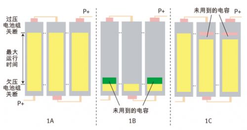
Figure 1: Effect of battery imbalance on battery capacity usage.
There are many reasons for battery imbalance:
* Non-uniform thermal stress
* Impedance variable
* Low battery capacity matching
* Chemical differences
Some of these reasons can be minimized by battery selection and better battery pack design. Even so, the main cause of battery imbalance in all previous design work was non-uniform thermal stress. The temperature difference between the battery and the battery can cause changes in impedance variables and chemical reactions. This creates a temperature difference, and the battery is exposed to this difference for a longer period of time (see Figure 2*). This is a laptop FLIR graph showing the extent of temperature differences, even in consumer electronics applications. For every 10 °C increase in temperature, the self-discharge rate of a lithium-ion battery doubles. A feature of lithium-ion batteries is that the internal impedance is a function of temperature. Lower temperature batteries exhibit high impedance, so the IR drop is greater during charging or discharging. This resistance also increases with exposure to high charge states and high temperature durations and extended charge cycle times.
Solution: Battery balancing technology
Due to the impact on energy supply and the risk of overcharging of lithium-ion batteries in tandem cell applications, battery balancing techniques must be used to correct for imbalances. There are two types of battery balancing technologies: passive battery balancing technology and active battery balancing technology.
Passive battery balancing technology
The passive cell balancing method known as the "resistance leakage" balance uses a simple battery discharge path that discharges the high voltage battery until all battery voltages are equal. In addition to other battery management features, many devices have battery balancing.
Lithium-ion battery pack protectors such as the bq77PL900 are used in many cordless battery-powered devices, power-assisted bicycles and mopeds, uninterruptible power supplies, and medical equipment. Its circuit mainly functions as an independent battery protection system, using 5 to 10 series batteries. In addition to the many battery management functions controlled through the I2C port, the battery voltage can be compared to a programmable threshold to determine if battery balancing is required. If any particular battery reaches this threshold, charging stops and an internal bypass is activated. When the high voltage battery drops to the recovery limit, the battery balance stops and continues to charge.
image 3
Figure 4
The battery balancing algorithm uses only voltage divergence as a balancing criterion and has the disadvantage of being overbalanced (or underbalanced) due to the presence of impedance imbalances (see Figures 3 and 4). The problem is that the battery impedance also causes voltage differences (VDiff_Start and VDiff_End) during charging. Simple voltage cell balancing does not distinguish between a power imbalance or an impedance imbalance. Therefore, this balance does not guarantee that all batteries will receive 100% of the charge after full charge.
One solution is to use a battery fuel gauge, such as bq2084. They all have improved voltage balancing techniques. Since the impedance difference between the batteries misleads the algorithm, it is only balanced near the end of the charge cycle. This approach minimizes the effects of impedance differences because the IRBAT voltage drop also becomes smaller as the charging current gradually decreases to the termination threshold. In addition, this IC also makes the balance judgment based on all battery voltages, so it is a more efficient implementation. Despite many improvements, this need to rely solely on voltage levels limits the balancing operation to the high state of charge (SOC) region and only works during charging.
Another example is the bq20zxx battery fuel gauge product line, which uses an impedance tracking balance method. This type of fuel gauge no longer attempts to minimize the effects of voltage difference errors, but instead calculates the charge (QNEED) required for each cell to reach full charge, as shown in Figure 5. This balancing algorithm turns on the battery balancing FET during charging to provide the required QNEED. This type of battery fuel gauge makes it easy to implement a QNEED-based battery balancing scheme because the total power and SOC are more stable in the monitoring function. Because battery balancing does not distort battery impedance, it can operate independently of battery charging, discharging, and even idle. More importantly, it achieves the best balance accuracy.
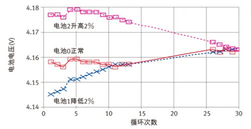
Figure 5: Battery balance based on QNEED.
Because of the limited balance of passive battery balancing techniques using integrated FET solutions, battery variations or imbalance rates may exceed battery balance. In addition, due to the low bypass current, it can take several cycles to correct for general imbalances. Battery balancing can be enhanced by designing some external bypass circuits with existing components (see Figures 6 and 7). In Figure 6, the internal balance MOSFET is first turned on when it is decided to balance a certain battery. This creates a low current path through the battery terminals (Battery 1 and Battery 2) and the external filter resistors on the IC pins. When the internal FET gate-source voltage is formed in the resistor, the external MOSFET is turned on. The disadvantage is that adjacent batteries cannot be quickly and simultaneously balanced. For example, if the adjacent internal FET is turned on, Q2 cannot be turned on because there is no current through R2.
Figure 6
Figure 7
Figure 7 shows the latest example of passive battery balancing. It is a low cost, single-chip battery fuel gauge solution. Unlike the battery fuel gauge solution described above, this IC does not have an internal battery balance, but requires a similar external bypass circuit to complete the balance. However, since the balance implementation circuit is an open drain inside the IC, it can simultaneously balance a few cells including adjacent cells. This balancing circuit uses an improved voltage algorithm, as shown in Figure 6. However, the external FET driver in Figure 7 describes a more efficient battery balancing method.
Active battery balance
Since 100% of the excess energy in a high-energy battery is dissipated as heat, passive balancing is not the preferred method during discharge. Active battery balancing uses a capacitive or inductive charge shuttle to transfer the charge between the cells, which is an extremely efficient method. This is because the energy is transferred to where it is needed rather than being released. The cost of doing this is to add more parts and costs.
The patented bq78PL114 PowerPump battery balancing technology is the latest example of active battery balancing using inductive charge transfer. It uses a pair of MOSFETs (N-channel and P-channel) and a power inductor to create a charge-transfer circuit between two adjacent cells.
The battery pack designer sets the imbalance threshold between the series batteries. If the IC measures an imbalance that exceeds this threshold, it will enable PowerPump. Figure 8 shows a simplified diagram of a buck boost circuit using two MOSFETs (Q1 and Q2) and a power inductor. The top cell (V3) needs to transfer energy to the lower cell (V2), and the P3S signal (operating at about 200 kHz and 30% duty cycle) triggers this energy transfer, and then the energy flows through Q1 to the inductor. When the P3S signal is reset, Q1 is turned off and the inductor energy level is at its highest level. Because the inductor current must flow constantly, the body diode of Q2 is forward biased, completing the charge transfer to the V2 position battery. It should be noted that due to its low series resistance, the energy stored in the inductor has only a slight loss.
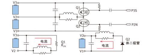
Figure 8: Battery balance using PowerPump technology.
Assuming that the length and capacity of the series battery are variable, there are some restrictions when transferring charge. One consideration is how far can we move energy before we no longer get energy supply optimization? In other words, how far can we move the charge before the converter's inefficiency exceeds the many benefits of balancing the battery? Using 85% of the estimated efficiency in our tests, PowerPump only transfers energy to less than 6 cells away. But what's important is that, in the case of ignoring efficiency, a “regional balance†must be achieved before the entire battery pack can reach full equilibrium.
In addition to these obvious advantages, the benefit of PowerPump battery balancing technology is that the balance may ignore a single battery voltage. This means that if you decide to transfer charge between two cells, it can be done during any battery operating mode sequence (charging, discharging, and resetting). The transfer can be completed even if the battery voltage at which the charge is supplied is lower than the battery voltage at which the charge is received (for example, a low voltage caused by a lower battery resistance at the time of charging or discharging). Compared to the "resistance leakage" balance, the heat loss of energy is small.
The following are three optional balancing algorithms:
* Terminal pressure (TV) extraction
* Open circuit voltage (OCV) extraction
* State of charge (SOC) extraction (pre-balance)
TV extraction is like the voltage passive battery balance described earlier. As shown in Figure 4, the TV balance during charging does not always produce a balanced amount of power that tends to end discharge. This is due to the battery impedance mismatch we mentioned earlier. The OCV extraction compensates for the impedance difference by estimating the OCV based on the battery current and battery impedance measurements.
Figure 9
Figure 10
SOC extraction works in a similar manner to impedance tracking devices, which calculates the exact charge level of each cell and transfers energy between the cells so that the battery is balanced at the end of charge (EOC) ( See Figure 9*). Looking at the discharge OCV map (see Figure 10*), we pre-balance each cell to an offset voltage that reflects its charge. A few percent difference in charge will cause a large difference in the lower part of the discharge curve. If we know 1% to 2% of the electricity, we can have a very close match at the end of the discharge. This is where you want to use the active balancing technology to get the best balance of your battery at the end of charging and at the end of the discharge.
Compared to traditional passive balancing techniques, PowerPump technology can better correct battery imbalances because higher component currents can be controlled by changing component values.
In notebooks, the effective balancing current is typically 25 to 50 mA, which is 12 to 20 times the internal bypass balance. With this advantage, active battery balancing can correct for power imbalances in one cycle (95% of the time).
In larger capacitive batteries, the results of PowerPump technology are even more different. It is necessary to consider the length of time a battery pack can be balanced when using voltage passive balancing. The only battery energy level is the positive balance that occurs in the discharge portion of a charge cycle. Therefore, only a few percent of the time for a large-capacity battery pack allows for balance. Therefore, many battery pack designers choose a current balance of 1 amp, or even more than 10 amps. This creates many thermal issues and the cost of large FETs. If PowerPump is used to achieve true uninterrupted balance possibilities, then these design barriers can be minimized.
The choice of external components determines how much current you balance. The peak inductor current is determined by the battery voltage, inductance, and turn-on time. The average current from the power battery for the entire cycle is equal to 0.5x (peak current) x duty cycle. In normal extraction mode, the duty cycle is 33%. For example, using a 15uH recommended inductor and assuming a peak current of about 460mA, we get an average current of 75mA from the power supply. This 75 mA current can appear for a long time. This keeps the entire system in equilibrium, so we exchange the most energy at the end of charging and at the end of the discharge.
The problem keeps coming up, "So how much balance current do I need?" No one likes to hear the answer to this question. "It depends on several aspects!" First, you need to know the imbalanced leakage you expect in a certain period of time. If your system has a 5% imbalance after a 20-hour 20-hour battery pack discharge, you will need to transfer a lot of energy. PowerPump FETs and inductors need to be sized accordingly. Alternatively, you can use the SuperPump option for the latest firmware. It allows you to have a larger duty cycle to move energy when certain measurements are paused during normal mode. As mentioned earlier, battery quality and heat dissipation control are important prerequisites in determining how much balance is available.
A safety benefit of active battery balancing is that we can track the time of a battery. We can track the net decimation of each cell, defined as the positive value of the drawn battery and the negative value drawn from the battery. If the net value of one battery is too high, it will cause too much energy to be received from other batteries, indicating that it is a bad battery. This is an integral part of the SOH calculation and is similar to other parameters such as battery impedance and full charge.
Summary of this article
Some emerging battery technologies that focus on safety and longevity typically have advanced battery balancing and efficient thermal management. As the new battery balancing technology tracks the balance required for a single battery, the life and overall safety of the battery pack has increased. Balancing the battery at each cycle avoids improper use of the battery, which is often the cause of more imbalances and early battery aging. Battery chemistry, structure, and applications are becoming more diverse, requiring battery pack designers to upgrade their technology.
Piezoelectric Ceramic Actuator Plate,Piezoelectric Bending Ceramic,Piezo Ceramic Diaphragm
NINGBO SANCO ELECTRONICS CO., LTD. , https://www.sancobuzzer.com