1 Introduction
This article refers to the address: http://
According to statistics, 70% of the traffic of 3G mobile communication networks occurs indoors, and most of the value-added services of 3G also occur indoors. Therefore, 3G indoor coverage will be an important embodiment of the mobile operator's brand image, and also an important factor for operators to attract users.
As a 3G standard with independent intellectual property rights in China, the TD-SCDMA system was launched in 2007 in 10 cities across the country. Shenzhen is one of them. So far, the construction, testing and optimization of TD-SCDMA indoor coverage network is nearing completion, and accumulated a lot of experience in these aspects. In order to provide experience for the subsequent TD network construction, this paper attempts to talk about the design points of the TD-SCDMA indoor coverage solution.
2 Signal source selection
The source of TD-SCDMA system mainly includes radio remote, baseband remote (BBU+RRU), and its indoor coverage can be selected according to actual conditions. Here are a few common scenarios:
(1) Multi-channel scheme using TD-SCDMA radio remote, that is, multi-channel signals of TD-SCDMA cover different floors. The program fully utilizes the role of multiple sources of TD-SCDMA and reduces the number of dry-use applications. It is necessary to consider whether the space of the cable well can accommodate multiple 7/8′′ or 1/2′′ feeders, and try to combine the branches of the original indoor distribution system with the 2G signals.
(2) The “single channel + dry release†scheme using TD-SCDMA radio remote is similar to the traditional 2G indoor distribution system. Due to the high working frequency band of TD-SCDMA and the large signal transmission loss, dry release is generally required. The advantage of this scheme is that the requirements for the wireline well are low, there is no need to increase the main feeder, and the amount of reconstruction work is relatively small; the disadvantage is that the number of dry discharge is large, and the uplink noise is increased.
(3) "BBU + multi-channel RRU" scheme, the BBU is placed in the equipment room, and the RRU can be installed on the appropriate floor. The optical fiber is transmitted between the BBU and the RRU, and the RRU is connected to the antenna through a coaxial cable and a power splitter (coupler), that is, the trunk uses the optical fiber, and the branch uses the coaxial cable. Since the loss of the signal transmitted through the optical fiber is small, the feeder loss of the system is reduced, and the use of dry discharge is reduced. The advantage of this solution is that the source installation location is flexible, and the RRU can be installed at a position that enables the source power to be fully utilized as needed; the disadvantage is that the new fiber needs to be pulled and the fiber is easily damaged. In addition, since the TD-SCDMA system is modified on the basis of the 2G system, most of the 2G systems have been constructed when the building has not been completed. Once the decoration is completed, many of the lines are no longer accessible, and it is difficult to re-pull the construction. Unable to re-route. Therefore, with this scheme, it is necessary to fully consider whether fiber routing is feasible in design. At the same time, due to the adoption of multi-channel RRU, proper consideration should be given to the space of the wiring well.
(4) "BBU + single-channel RRU" scheme, the principle and scheme (3) are the same, and have the advantages of schemes (2) and (3). Since a plurality of single-channel RRUs are used, the dry release can be basically eliminated, and the disadvantage of requiring a large amount of dry release in the solution (2) is avoided. However, as with solution (3), it is necessary to consider whether fiber routing is feasible.
3 trunk amplifier design
Among the above four schemes, the use of dry discharge seems to be a disadvantage. However, due to the complexity of the indoor distribution system, dry release is not only indispensable, but the proper use will also benefit the low power output of the TD-SCDMA source.
As mentioned earlier, once the owner has renovated, many places cannot re-feed the feeder or fiber. In this case, it is necessary to install the TD-SCDMA source and the original 2G equipment room, make full use of the trunk line of the 2G system, and add TD-SCDMA dry-displacement where needed. As an active device, the introduction of dry-discharge, in addition to making up for the lack of power of the source, will inevitably bring about certain noise, and it is necessary to avoid disadvantages. The following describes the different uses and commissioning points of TD-SCDMA dry release.
3.1 Effects of amplifiers (relays)
Figure 1 Interference from indoor repeater
The principle of dry-discharge and repeater is the same. In the indoor distribution system, if the dry-discharge measurement is not good, there is also the situation in Figure 1, that is, the non-dry-discharge coverage area will be blocked due to the interference of the dry-discharge coverage area.
3.2 dry joints
The TD-SCDMA dry release cannot be connected in series because the noise is difficult to control after the series connection, and it is easy to cause interference to the base station.
Figure 2 dry parallel diagram
As shown in Figure 2, dry-discharge parallel is allowed, but it is adjusted so that the uplink noise of each dry-distribution arrives at the base station is basically the same and balanced. Otherwise, the dry-pad coverage area with small uplink gain is also subject to large uplink gain. Blocked by dry noise interference.
3.3 Adjustment of up and down gains in dry conditions under different conditions
The principle of dry release gain adjustment:
Downstream gain for dry release = upstream gain (recommended).
In some cases, the uplink and downlink gains may also be different, but the difference should be controlled within 5 dB; more than 5 dB of system performance will be affected. For example, when the uplink gain is less than the downlink gain of more than 5 dB, the uplink coverage may be insufficient.
The following is a list of adjustments to the dry-release gain in several cases:
(1) When the number of dry discharges in each channel is the same

Figure 3 The same number of dry and discharge channels
S0=Ppccpch-10*lgN, N=Number of channels used for indoor coverage.
Gain setting:
Method 1: S1 = S2 = S3 = S4 = S0 (recommended);
Method 2: If it is not desired that S1 to S4 are equal to S0, then (a) calculate L1 to L4, then G1 = L1, G2 = L2, G3 = L3, G4 = L4; (b) at S1 = G1 = S0 Based on the adjustment, calculate Δ=S1-S0, then G2new=G2old+Δ, G3new=G3old+Δ, G4new=G4old+Δ.
(2) When some channels are not dry
Figure 4 Part of the channel without dry
S0=Ppccpch-10*lgN, N=Number of channels used for indoor coverage.
Gain setting:
Method 1: S1 = S2 = S3 = S4 = S0 (required);
Method 2: Calculate L1 and L2, then G1 = L1 and G2 = L2.
Note: It is not allowed in any situation that S1 and S2 are not equal to S0.
(3) When the number of dry discharges in each channel is not equal
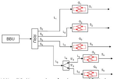
Figure 5 The number of dry discharges varies from channel to channel
S0=Ppccpch-10*lgN, N=Number of channels used for indoor coverage. S'0=S0-L0-Ls, Ls is the power loss, which is 3.3dB.
Gain setting:
Method 1: S1 = S2 = S3 = S0, S4 = S5 = S'0 (recommended);
Method 2: If S1~S5 are not expected to be equal to S0, then (a) calculate L0~L5, then G1=L1, G2=L2, G3=L3, G4=L4+L0+Ls, G5=L5+L0+ Ls; (b) Adjust on the basis of S1=G1=S0, calculate Δ=S1-S0, then G2new=G2old+Δ, G3new=G3old+Δ,..., G5new=G5old+Δ.
(4) When there are both dry and non-dry coverage areas on the channel
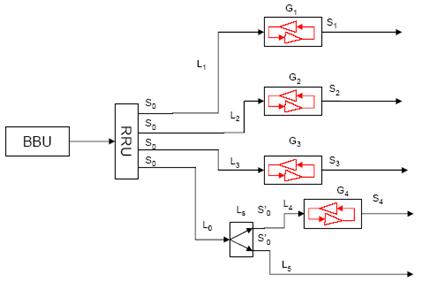
Figure 6: There are both dry and non-dry coverage areas on the channel.
S0=Ppccpch-10*lgN, N=Number of channels used for indoor coverage. S'0=S0-L0-Ls, Ls is the power loss, which is 3.3dB.
Gain setting:
Method 1: S1 = S2 = S3 = S0, S4 = S'0 (required);
Method 2: Calculate L0~L4, then G1=L1, G2=L2, G3=L3, G4=L4+L0+Ls.
Note: It is not allowed in any situation that S1 and S2 are not equal to S0.
In addition, the downlink gain does not have to be equal to the uplink gain. After accurate adjustment, the optimal downlink gain = path loss before the amplifier. at this time,
If the uplink gain = the optimal downlink gain, then the bottom noise of the base station side is just increased by 3 dB, and the indoor coverage system works normally;
If the uplink gain is <best downlink gain, then the bottom noise of the base station is increased by less than 3 dB. If Δ does not exceed 5 dB, the indoor coverage system works normally;
If the uplink gain > the optimal downlink gain, the base noise of the base station is increased by more than 3 dB. If the Δ does not exceed 5 dB, the indoor coverage system works normally.
Conversely, whether the uplink gain needs to be adjusted and how to adjust can be determined according to the system operation and the base station noise.
4 antenna design
Due to the indoor propagation environment and engineering considerations, the TD-SCDMA indoor distribution system cannot use smart antennas, but still dominates the omnidirectional ceiling antenna. Compared with the 2G indoor distribution system, the TD-SCDMA system has high frequency, large space loss and poor diffraction capability. Therefore, it is necessary to increase the number of antennas according to the actual coverage effect to ensure network coverage of TD-SCDMA. The antenna design is based on the principle of “multi-antenna low powerâ€, and the antenna is installed near the door as much as possible.
The EMC standard defines: the total power of the antenna port is <15dBm, and the pilot power of the antenna port is <7dBm. The indoor minimum fringe field strength MinRxlev=-85dBm, then the antenna port power minimum is: (-85)+68-2+13=-6dBm. Taking PCCPCH as a reference, 68dB is the theoretical propagation loss when the coverage radius is 15 meters, 2dBi is the antenna gain, and 13dB is the slow fading and interference margin.
The structure of the indoor coverage area is relatively complicated, and the antenna to the coverage area is often blocked. The antenna port power and antenna density should be designed according to the actual situation. In addition, when the antenna is closer to the mobile phone, in order to prevent the mobile phone receiving signals from exceeding the power control range and causing blocking, the antenna port pilot power is generally required to be between -6 dBm and 7 dBm.
5 GPS sync antenna design
Like CDMA2000, TD-SCDMA also requires GPS to provide a synchronous clock inside the system. The base station synchronization clock can play a key role in cell handover. Therefore, GPS is an indispensable part of the TD base station; without it, the TD base station cannot perform normal handover with other neighboring cells. To obtain synchronization information, the TD base station needs to receive at least 4 satellites. According to the actual engineering experience, the following points should be considered when selecting the GPS antenna position:
(1) The unobstructed range of 45° around the GPS antenna is the most ideal installation environment;
(2) There is no metal object blocking near the GPS antenna, otherwise it will easily cause the receiving satellite to be unstable;
(3) The GPS antenna cannot be too close to the wall, and the empirical distance is more than 3 meters. When selecting the installation location, first make sure that at least one of the north-south direction is not blocked within 45° of the top of the GPS antenna, and both sides are secondary.
A Phone Screen Protector is an accessory for cell phones, Pads, tablet computers, and other devices that protects the screen and keeping your screen intact.
phone screen protector preserves your screen from scratches that can happen in everyday encounters, not to mention the rough and tumble environment of your bag. You can feel confident knowing your shield may take a beating, but your phone's screen will remain as smooth and clean as the day you bought it .
iPhone 6 plus screen protector makes your lovely iPhone 6 plus Screen Clean and Pristine. It can prevents oils from adhering to your screen which means smudges and fingerprints wipe away easily.
You can get glass phone screen protectors made out of tempered glass. Like with any technology, they have their own pros and cons.
Our screen protector use for , iPhone 6 , iPhone 6 plus , 7 plus , iPhone 8 , 8 plus and etc .
Phone Screen Protector
Phone Screen Protector, Clear Phone Screen Protector, Smart Phone Screen Protector, Glass Phone Screen Protector,Phone Glass Protector
Hebei Baisiwei Import&Export Trade Co., LTD. , http://www.charger-cable.com