The CDC3207G developed by Micronas of Germany is a 32-bit ARM core high performance low power microcontroller. This is a microcontroller designed specifically for automotive dashboards. It has been applied to high-end cars such as Volkswagen, China Dongfeng. The CDC3207G uses the ARM7TDMI core with 512 K Flash and 32 K SRAM. In order to meet the needs of automotive instrument design, the microcontroller also provides 16 10-bit A/D conversion modules, audio driver modules, LCD driver modules, and 7 channels. Stepper motor drive module, etc. Moreover, the CAN communication module is integrated internally, which can easily communicate with other electronic devices in the car.
2 hardware design
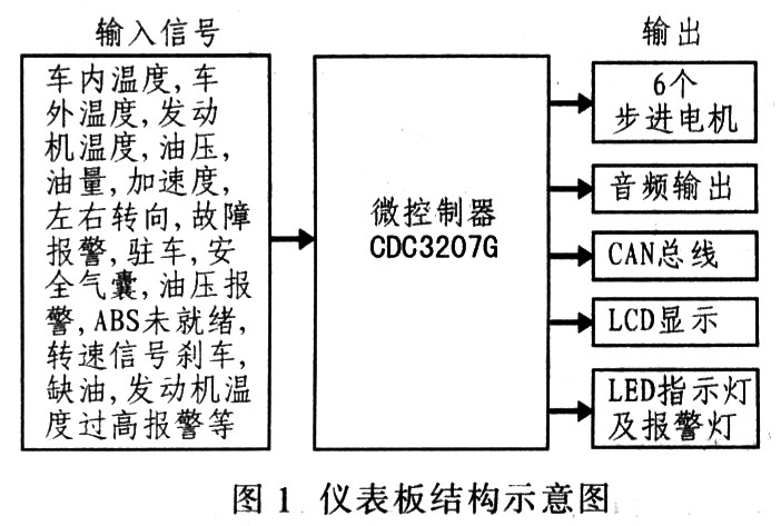
2.1 Overall Hardware Diagram The entire dashboard is controlled using a CDC3207G microcontroller. The input signal can be divided into two types: digital switch signal and analog voltage signal. For digital switching signals, their status can be read directly according to their high and low levels. For analog signals, such as speed, speed, etc., the A/D conversion is performed by a 10-bit precision A/D converter inside the microcontroller to convert the analog signal into a digital signal. The instrument panel is designed to drive six hands with six stepper motors for speed, engine temperature, fuel, speed, oil pressure and battery voltage. The sounds and fault alarms that are emitted when turning left and right can be driven by a speaker to output a speaker. In addition to generating a simple tone alarm, a click signal with a gradually decreasing amplitude can be generated. The current gear position, temperature inside and outside the car, and some alarm information and time can be displayed on the LCD. The LED indicator can be driven directly from the H port of the microcontroller. The CAN bus can communicate with other control modules in the car. Figure 1 shows the structure of the instrument panel.
This article refers to the address: http://
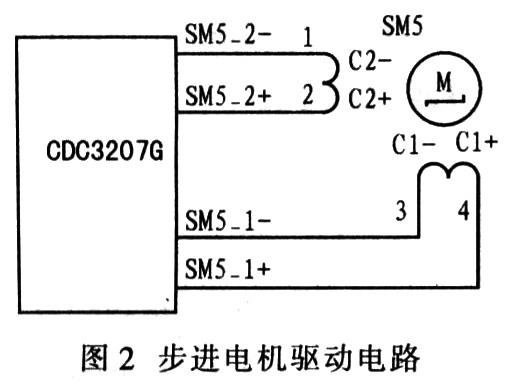
2.2 Stepper Motor Module The application of stepper motor in the field of automotive instrumentation is the most prominent feature of the new generation of automotive instrumentation. The controller CDC3207G integrates 7 stepping motor drive modules. Each stepper motor module is connected to the four high-current output ports of the H-bridge through the controller to directly drive the two-phase stepper motor, which greatly simplifies the hardware circuit. design. Various pulses required for stepper motor positioning can be generated by software. The stepper motor module of the CDC3207G microcontroller provides multi-channel PWM output. The output signal frequency can be selected through hardware settings, and the offset of the output signal timing of different stepper motor modules can improve the electromagnetic compatibility performance (EMC). According to the needs of controlling two-phase stepper motors, the CDC3207G internally provides three 8-bit registers for software to generate the pulse signals needed to control the stepper motor. Two of the registers are compared with the module timer by the comparator in each module to generate the PWM signal of the drive motor, and another register is used to select the corresponding stepper motor module, output the drive signal, and select 4 output pins. Polarity. In this way, each stepper motor can be conveniently controlled by software operation on three registers. In addition, the CDC3207G also has a zero detection function, that is, detecting the induced current when the motor is running, and obtaining the position information of the motor running, it is possible to determine whether the motor reaches the initial position (ie, the zero position of the automobile meter). Figure 2 shows the stepper motor drive circuit.
2.3 Audio Control Module
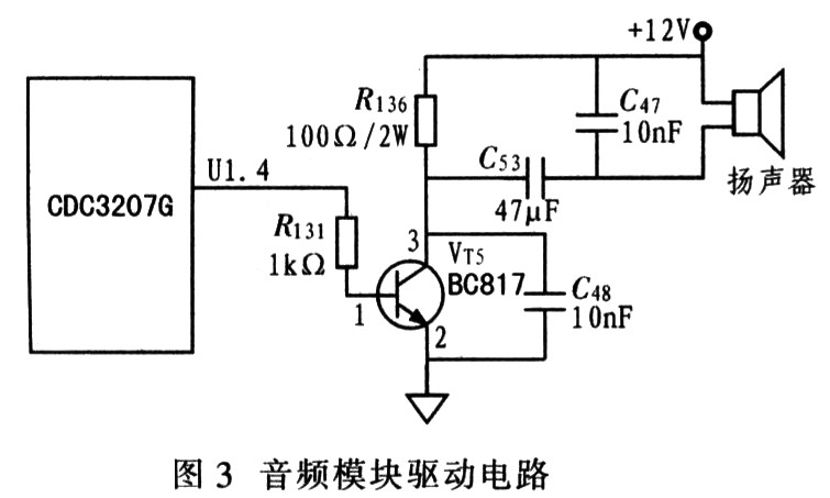
   The output signal of the CDC3207G audio module can directly drive the buzzer or other audio equipment, and the hardware design is relatively simple. Figure 3 shows the audio module drive circuit. As can be seen from the figure, the entire audio circuit can be designed by directly connecting the triode VT5, the low-pass filter circuit and the speaker at the output port U1.4 of the microcontroller audio module. The audio module is used to consist of a pulse width modulation unit (PWM), three counters, and one accumulator. The module can generate a sound signal similar to the click sound, which is a square wave signal with adjustable frequency. The pulse width of the output signal is determined by the pulse width of the square wave signal, and the exponential change of the signal amplitude can be realized without the CPU.
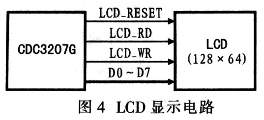
2.4 LCD display module Liquid crystal display (LCD) has the advantages of micro power consumption, flat panel, no x-ray and electromagnetic radiation. The LCD display module can accurately display various physical quantities in numbers and images, and adds some text prompts when a fault occurs. The CDC3207G integrates a 48x4 pen segment LCD driver module that can drive 4 rows and 48 columns of LCD display modules. In order to display more information, here is a 128x 64 LCD module, the driver is integrated on the LCD module, so the LCD driver inside the CDC3207 is not used. Figure 4 shows the LCD display circuit, which needs to connect 8 data lines, one read signal, one write signal, and one reset signal line.
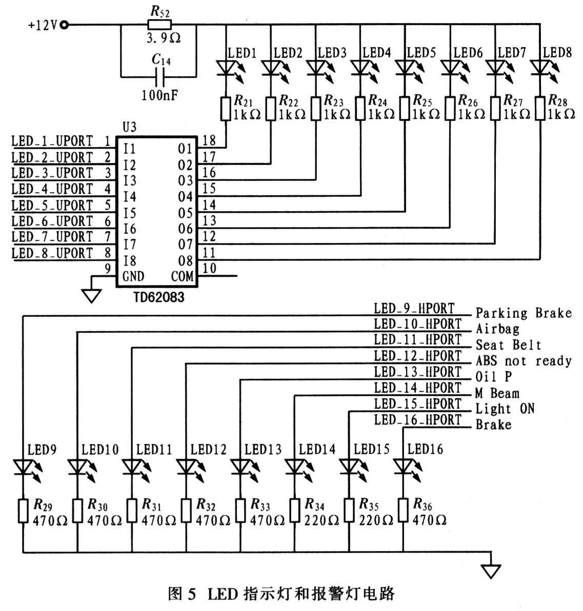
2.5 LED indicator and warning light LED indicator can be driven by H port with strong driving capability, and its 8 LED indicators are directly driven by H port. However, the H port is not enough, so a TD62083 is extended to drive the other 8 LED indicators and warning lights. Figure 5 shows the LED indicator and warning light circuit.
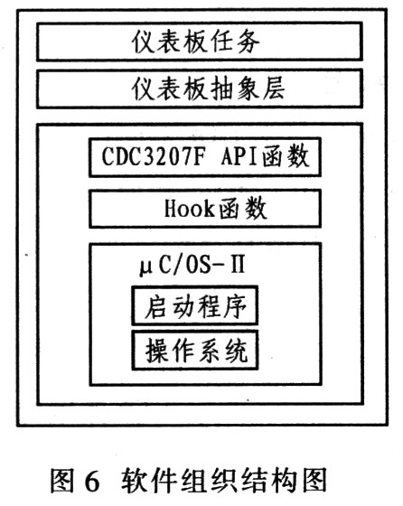
3 Software design Taking into account the real-time requirements of the car dashboard, the μC/OS-II operating system development software is applied. μC/OS-II is an RTOS with the characteristics of modern operating system. It has clear structure, detailed annotation, good scalability and portability, and is widely used in microprocessors of various architectures. The system composition of μC/OS-II includes basic functions such as task scheduling, task management, time management, and communication between tasks. Here, only the allocation of the startup program and tasks of μC/OS-II is briefly introduced, and the focus is on the transplantation and application based on CDC3207G. Figure 6 shows the organization of the software.
3.1 Design of the startup code The embedded system has limited resources, and the program is usually solidified in ROM operation. Before the ROM program is executed, the system hardware and software running environment need to be initialized. These tasks are completed by the startup program written in assembly language. The launcher is the beginning of the embedded program, which is solidified in the ROM along with the application and runs first after the system is powered up. It should contain all the segment classes that may appear in each module and arrange their order appropriately.
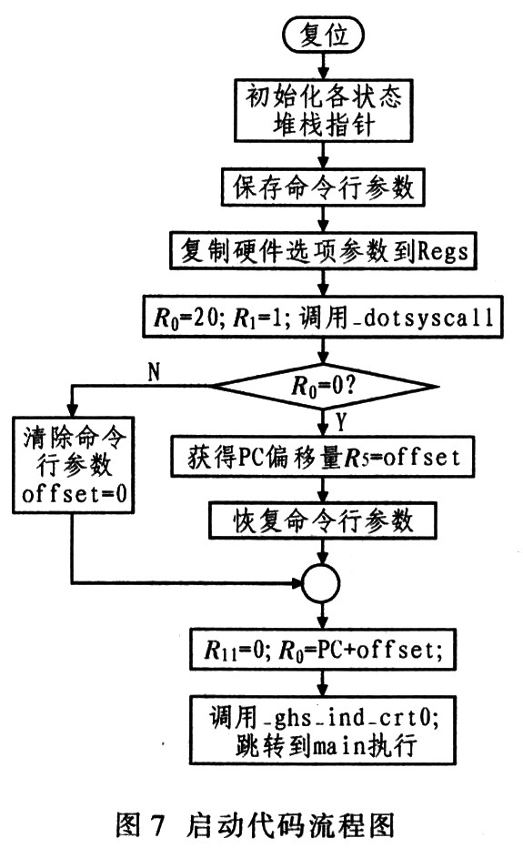
The key to designing an excellent embedded program is to have a good startup program. Since μC/OS-II is not designed for specific hardware, the μC/OS-II kernel code can be divided into four parts: processor-independent code, and Processor-related code, application-related code, and driver libraries. In order to enable the μC/OS-II to operate normally on the ARM7TDMI-based processor CDC3207G, it is necessary to implement the corresponding startup program and the design and implementation of the processor-related part in μC/OS-II. Figure 7 shows a flow chart of the startup code.
3.2 Task Planning The development of the dashboard can be done in several parts of the software. The following questions are planned.
(1) Start the task Priority: 10
Cycle: No Deprivation: No Effect: Initialize each module, including UART, timer, capture comparator, etc. (2) Stepper motor task Priority: 8
Period: 2 ms
Deprived: No Effect: Drive stepper motor, need 0 position detection at startup (3) Indicator task Priority: 7
Period: 500 ms
Deprived: No Effect: Set the indicator and tone.
(4) Collection task Priority: 6
Period: 25 ms
Deprived: No Effect: Used to collect various non-interrupted sensors such as temperature, light intensity and other sensor signals and save (5) Backlight task Priority: 5
Period: 250 ms
Deprived: No Function: Adjust the backlight of the instrument panel and LCD according to the surrounding light intensity (6) LCD display task Priority: 2
Period: 100 ms
Deprivation: It is a task: update the LCD display according to the data collected on the bus. For example, the above tasks are running at the task level, such as temperature and kilometers, and some tasks are running at the interrupt level, such as clock tick interrupt, CAN bus data acquisition, etc. .
4 Conclusion Because Micronas' CDC3207G integrates stepper motor drive module, audio control module, LCD driver module, LED and alarm light drive port, CAN bus module and other rich resources, it reduces the need for external drive devices. The quantity greatly simplifies the design of the dashboard system. The device consumes very little power during sleep (tested to be approximately 19.1μA), which helps reduce overall system power consumption. The dashboard system performs well in all aspects. The pointer rotates smoothly, has extremely low power consumption, and has high reliability. The software part uses the uC/OS-II operating system, which has good real-time performance and can respond quickly to external events.
Solar power system inside,energy saving, easy for repairing. Soft light and beautiful appearance, for decorating, used in park, garden house and green belt. Solar Lawn Lamp used all-Aluminum Construction with Strong and Elegant Pole, Perfect decorative effect by down light, our solar lawn lamp used 100% solar powered, wireless connection and over 2 night long lighting time, waterproof IP65.
Solar Lawn Lamp
Solar Lawn Lamp,Landscape Lighting,Lawn Lights,Solar Yard Lights
Yangzhou Urban New Energy Co.,Ltd , http://www.urban-solarenergy.com