The devil continued to rain, and the new aircraft I got back on Tuesday had no chance to play. However, it also takes some effort, and it needs to be refitted, and the accessories that need to be purchased are all available.
Regarding which parts need to be purchased and which parts are suitable for modification, I will explain in detail in another main post. Today, we will share the process of converting the DJI remote controller to your friends (flying friends) and hope to help everyone.
Suitable for modified objectsAs long as you use the DJI Lightbridge digital remote controller, it is suitable for conversion. Including the common Wizard 3 series, including the A version and P version. Because P3S and P3 4K are still the last generation of analog images, the effect is not as good as that of digital images after modification. Therefore, it is not recommended. Elf 4 and Inspire series.
You can compare your own aircraft model, if you are in this one, then congratulations, your remote control is a modified value, then this article will be useful to you.
Modification principleThe original remote control antenna is an omni-directional antenna, and the DJI antenna interface is not a standard interface. To modify the extended range, a more effective method is to increase the transmission power or change the direction of the antenna. I think the early Elves 2 players, installed the image transmission, all know that our display (I use the best known at the time as the Eagle View) on the left and right 2 change each installed an antenna, directional antenna + omnidirectional antenna. The antenna in the lower right corner of the following figure is.
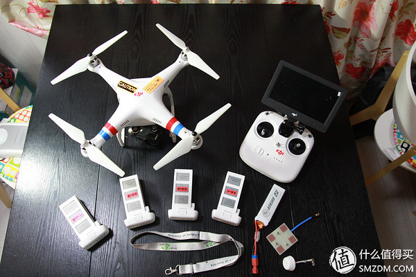
It can be seen literally that the omnidirectional antenna has better directionality but a slightly shorter distance. The directional antenna is the opposite.
buyThere are many sellers on Taobao. They are all selling this product. They have more reviews and good reputation. The success rate will be higher.
There is also a place to pay attention to, Inspire and Wizard Series
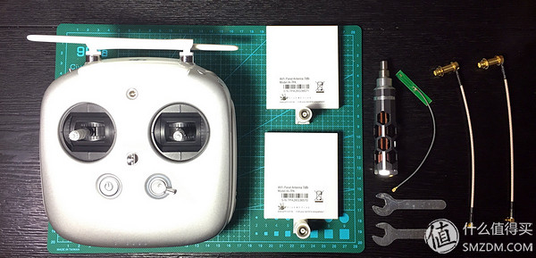
Modification processAfter waiting for 2 days, SF Express took things to my home. I'm taking a photo with the inspire remote control I want to change. Although the seller sent two screwdrivers, I was still accustomed to using my own tools.
First, turn the remote control over and use the Allen screwdriver to remove the four screws in the red box below.

The second step, gently pull the plastic shell. Because the Inspire remote is born with HDMI video output, it has 2 more interfaces than the Genie series (of course the Genie series needs the HDMI output function, and you can also separately purchase the HDMI output module to replace it to achieve this function).
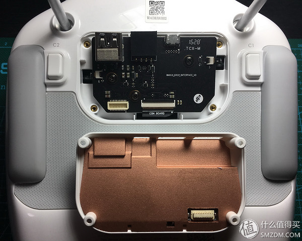
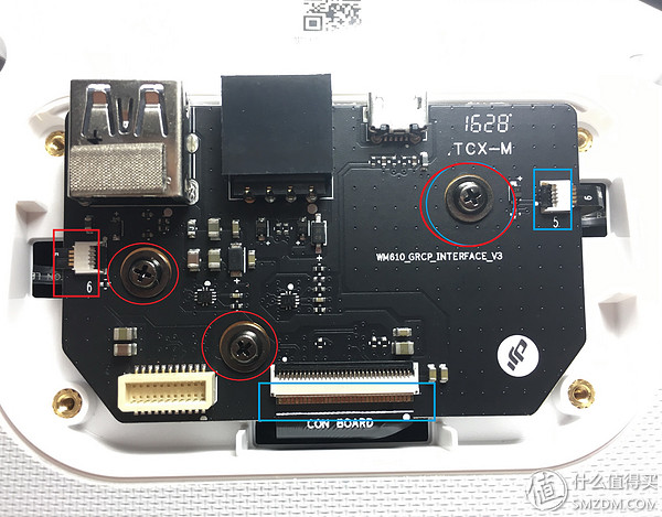
The third step is to remove the three Phillips screws from the red frame. By the way, the three data lines of the basket (I'm sorry the picture is not processed, the left-most box is blue) are pulled out. Put. There is no "authority" for this interface.
HDMI output board, if damaged or want to be modified, can be purchased separately
After completing the above steps, it can be successfully removed
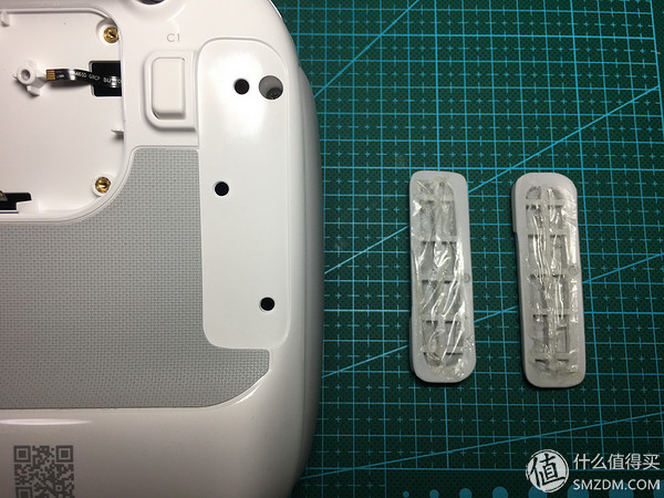
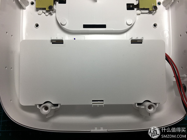
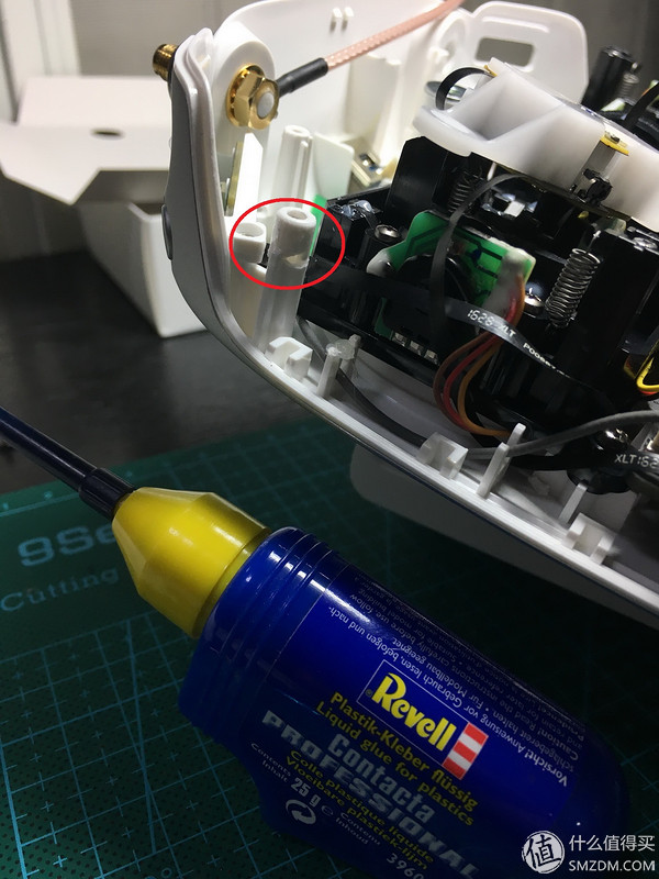
In the fourth step, remove the 2 long rubber pads and 2 small round rubber pads of the remote controller. The rubber pad and the remote control are glued together with double-sided adhesives, so just use force.
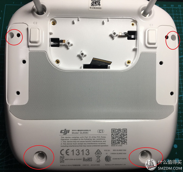
In the fifth step, the purpose of disassembling the rubber pad is to expose the screw holes. The four Phillips screws in the red circle below are removed. It's a little tight, but it's easy to split. I have to dramatize here beforehand. The quality of this batch of remote controls is absolutely problematic, either because there are problems with the material (recycled plastic) or there is a problem with the assembly process (tightening the screws with excessive torque). Just removing the screws, it was found that the plastic posts inside had broken, and there was more than one, almost 50% of them. Some of the fixed posts were comminuted and could not be repaired.
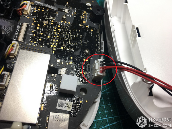
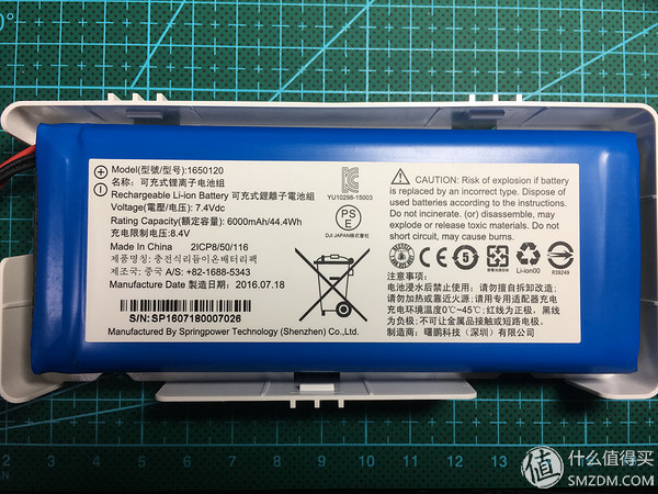
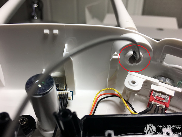
In the sixth step, remove the back of the plastic remote control. Be careful here that the remote battery is fixed to the back and a wire is connected to the motherboard. Remember to remove it first.
Remote control back
The 7.4V 6000mAh battery is not Samsung's.
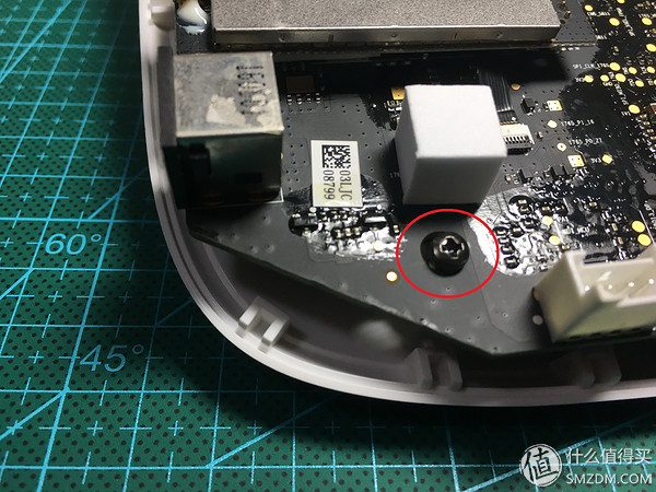
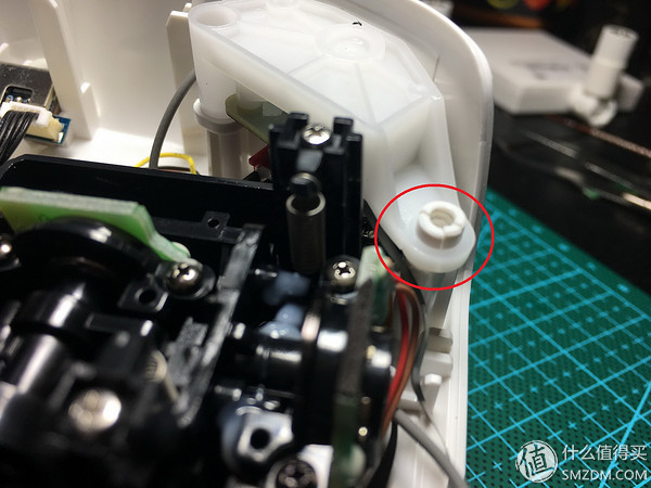
 The colleague who was removed from the back cover found that the plastic column had fallen off. This is still the best, at least it is divided into two parts, I glued together. The location is the charging port, which holds the back of the remote control (in the picture with 4 screws above it, the screw is located at the bottom left).

Trying to screw it up and see it seems to have little effect. However, the actual situation is that in the final place, the screw does not exert any force at all, and only the screw hole is filled with the hot melt adhesive, and then the screw is extended to the end.
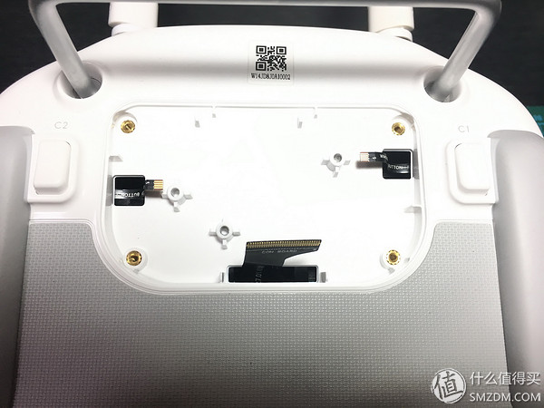
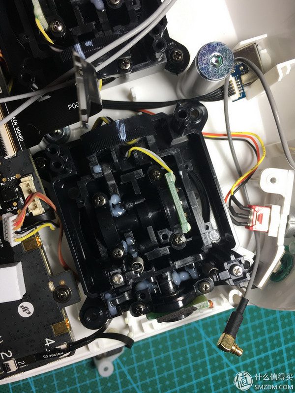
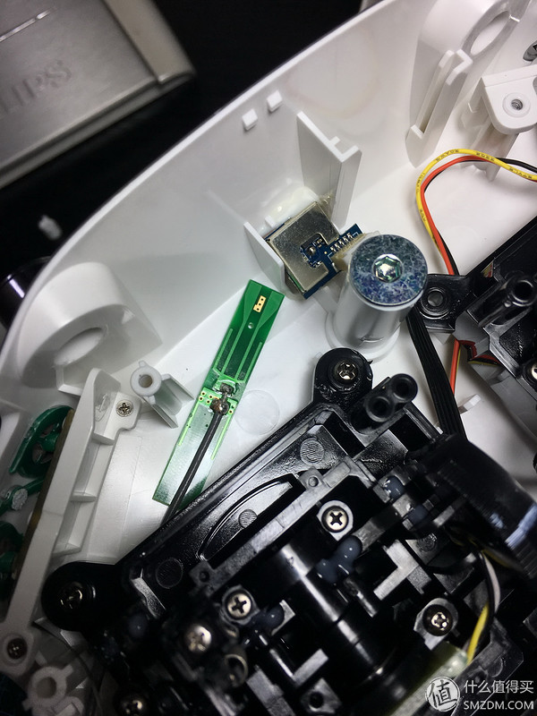
In the seventh step, the antenna to be modified this time is a versatile antenna, so it is necessary to remove the original one. The three feeder connectors in the red frame below should be unplugged first. The reason that the inspire is not universal with the Genie series remote controller is that there is a 5G signal line on the left. I consulted, this is the dual control operation, the master and deputy control for flight data exchange.
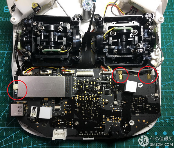
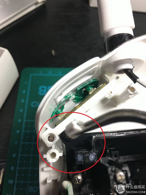
Also found a broken plastic column. It was this place that was dismantled and divided into four pieces that could not be bonded at all. Finally, it can only be fixed with hot melt adhesive. Here I spent 30 minutes more to adjust my position. Here is the control of the camera up and down position, pulsator adjustment. It can neither hinder the normal use of the pulsator, it can be rolled, there is a need to firmly fix the position, otherwise the pulsator will hit the outside frame and it will affect the use. The pulsator is not linear enough. When the camera is tilted, it will not be linear, and the resulting film will not be effective. Remind everyone that you also want to modify your flying friends. If you find that after opening the remote control, many plastic posts break, you can quickly fix it with glue and then go down. Otherwise, once it is taken down, it will not be able to reply anymore. This plastic material is really bad!
 In the eighth step, remove the 5G feeder. This feeder is the biggest difference between inspire and Genie. The original factory was wrapped in hot melt adhesive.

All that needs to be done is to clean the glue and then unplug the feeder connector.

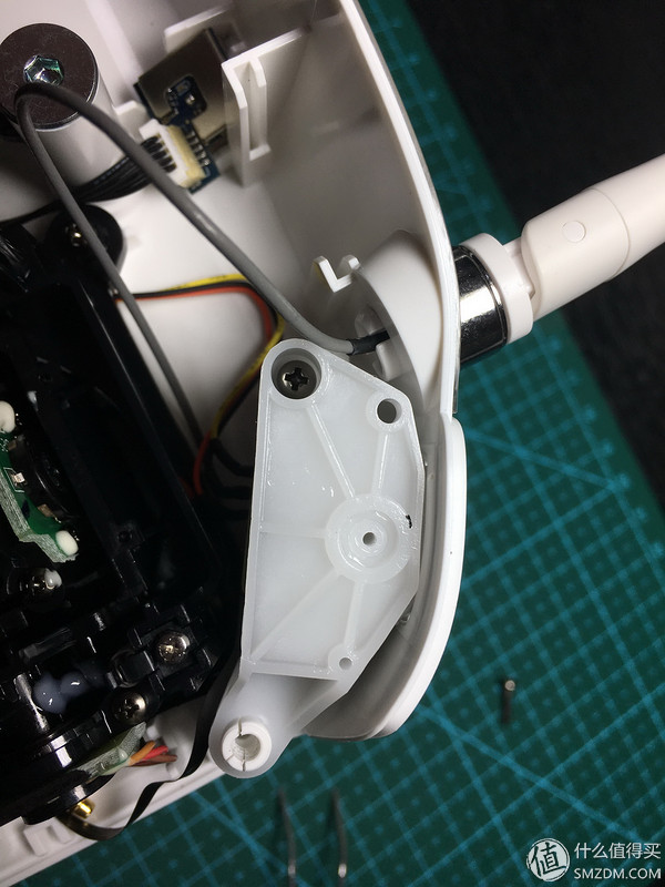
In the ninth step, I originally wanted to dismantle the antenna on the left side. As a result, I found that a plastic holder had broken. The mood is extremely bad.
The tenth step, still start from the right. Unscrew the screws and the entire pulsator assembly can be removed.
Hey, this is completely finished.
In the eleventh step, the front two feeders can be taken out here.
Inside the original antenna, it is fixed in a plastic snap.
Knowing the principle, it is not difficult to remove it. The twelfth step, a pair of needle-nose pliers, and then push out forcefully out.

In the thirteenth step, after removing the antenna, I removed the four screws in the red circle in the figure for convenience.

Removed antenna
In the fourteenth step, first install the 5G antenna. Then remember to put on hot melt adhesive.
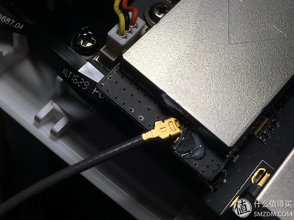
In the 16th step, replace the feeder on the left. The new feeder is much thicker than the original feeder. And the new joints no longer need to be processed on the EV pulsator. The antenna connector is a universal model, so you can choose the type of external antenna yourself, and you can even choose the car antenna. The remote control transmitter antenna guides the outside of the car, so that summer can hide in the car blowing air conditioning, watching the screen remote control aircraft.
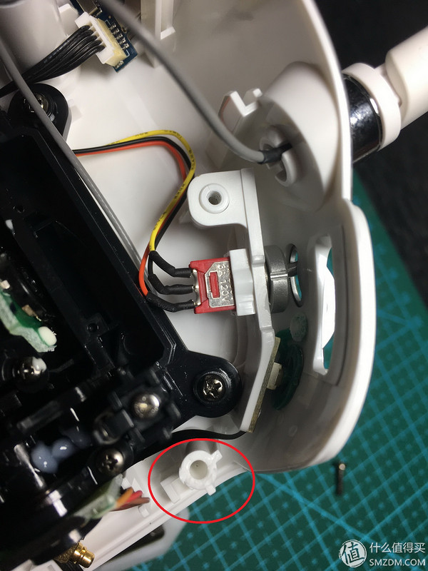
The following place was broken into 2 cuts, and it was solved with glue. Has not found that there is still a small piece.
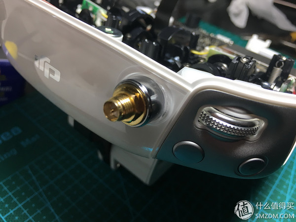
The antenna is fixed on the outside with washers + screws
In the seventeenth step, the other side is also the same. I'm sorry to forget to take pictures when loading 2 left and right feeders. The principle is that the line should not be pressed by other components as far as possible, and follow the trend of the feeder line. Card to the original interface, pay attention to the correct location. The correct position to enter the card, there will be a buzzing sound. After the card is in, try to turn it around. If it is smooth, there is no problem. The left antenna is plugged into the right interface and the right antenna is plugged into the left interface. In fact, this is a very important picture. My suggestion is to first insert the feeder on the interface, then route it in place, and finally send the connector out of the remote controller.
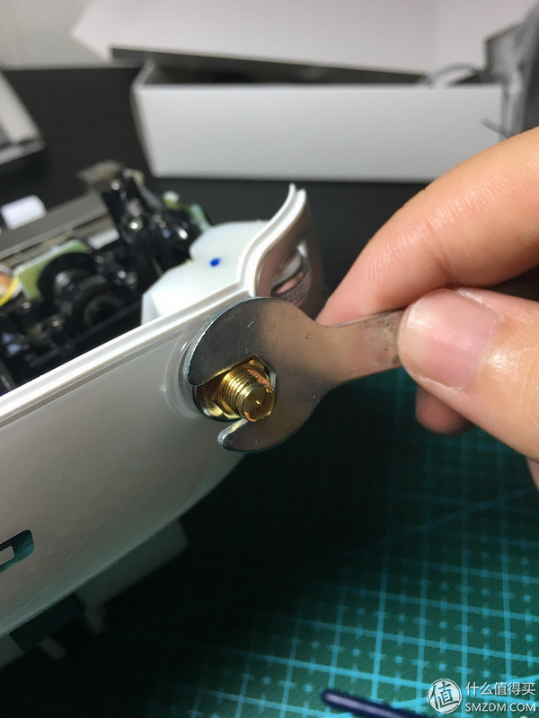
In the eighteenth step, the pulsator assembly is retracted, and then the nut can be tightened externally with the included wrench. If the pulsator assembly is installed, remember to try it out and make sure that there are no problems before proceeding to the next step.
The nineteenth step is the longest one. In accordance with the above order, the battery power connector is installed, before loading the remote control back, remember to wear the widest of the three data lines out, and then fix the back of the 4 screws (here, I use a lot Hot-melt adhesives help), good rubber pad. Plug the three data cables back in. Tighten the three screws on the HDMI module. Finally, replace the cover and tighten the four screws. This completes all modifications to the remote controller's extended range.
When screwing back, don’t use too much force and feel “eat†tight enough. You still have concerns that screw glues and hot melt glues can be used according to actual conditions.
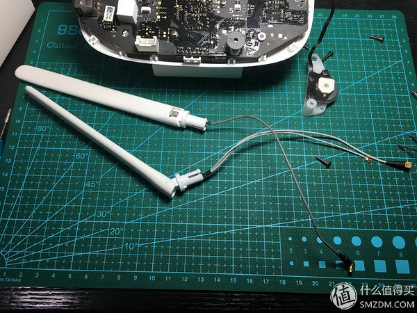
Modified effectThe effect said here is definitely appearance. This time, I deliberately chose a white directional antenna because I was already using P3P for black.
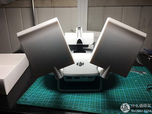
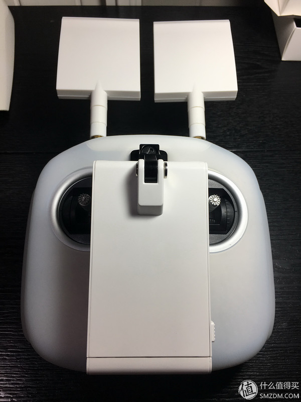
The mobile phone/PAD bracket has also been replaced, so even the 9.7-inch iPad Pro is stable.
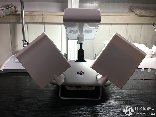
From another angle, put on a white silicone sleeve.
Take off

After all the equipment was installed, the remote controller was deliberately tried and the necessary inspections were performed. Inspection items: 1, charge, OK . 2, open the remote control power supply, OK . 3, the remote control normal control aircraft deformation, OK . 4, remote control diagram transmission to iPad, OK . 5, left and right 2 side pulsator, OK . 6, the bottom of the remote control C1 & C2 button, OK . 7, iPad touch screen, control the camera 360 ° & up and down rotation, OK .
to sum upBecause P3P has been using the modified antenna and flying together with the flying friends, my directional antenna has obvious signal anti-jamming and graphic transmission stability. In the final analysis, the extended range of the remote control, although nominally called extended range, is more to ensure the safety of the flight. Therefore, I personally recommend flying friends. Of course, if your personal ability is slightly weak, or your home tools are not very homogeneous (in fact, in addition to the attached tools, home glue guns and needle-nose pliers are enough), you can let the shop help you change. The disadvantage is that you need to express the remote control and then pay extra.
Well, this time, the personal experience sharing related to drones has come to an end. It's free on weekends. I'll write one. The DJI Elf series carries a history of change.