In recent years, the sales volume of high-voltage power supply industry in China has developed rapidly, and the production quality of high-voltage power supply has also increased. As an important component of high-voltage power supply, protection circuit has a broad development prospect. The protection circuit can effectively protect the internal circuit, protect the high-voltage power supply and the electrical equipment, prolong the service life of the high-voltage power supply and the electrical equipment, and more importantly provide the operator with a more secure guarantee. Therefore, it is necessary to design a protective circuit. And important.
High-voltage power supply overall circuit structure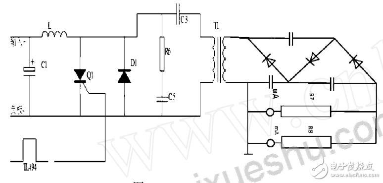
A complete high-voltage power supply is shown in the figure, which mainly includes six parts: auxiliary power supply, inverter unit, pulse oscillation control unit, voltage doubler rectifier unit, high voltage measurement unit and protection unit. The output voltage of the high-voltage power supply is generally above. It is protected by a well-established protection circuit between the voltage doubler rectifier unit and the high-voltage measurement unit, which can extend the service life of the high-voltage power supply and various parts, and prevent high-voltage power supply and power supply. The product is burned out and can improve the safety of the experimental operator's personal safety. It can be seen that the protection circuit is quite important.
Design Scheme of Overvoltage Protection Circuit of Pulse Oscillation Module Based on LM358The purpose of the protection circuit
The sampling circuit is pumped to the in-phase input terminal of the LM358 by the sampling resistor. The inverting input terminal of the LM358 is connected to the 14 pin of the TL494 (built-in 5V reference voltage). If the sampling voltage is lower than 5V, the LM358 does not work. If the sampling voltage is higher than 5V, the LM358 outputs a high level, and the output of the LM358 is connected to the 4th pin of the TL494. Once the LM358 outputs a high level, the voltage of the 4th pin of the TL494 will be higher than 3.5V. At this time, the TL494 4 The foot will control the TL494 to stop the external output pulse, and then the entire high voltage power supply circuit will be in the off state and stop working.
Sampling circuit design
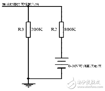
In the high-voltage sampling section, in order to ensure safety, a voltage analog circuit is used for sampling, and the current of the analog circuit is equal to the current of the high-voltage output. Assume that the output current is 25μA when the high-voltage output is outputting 25000V, so an analog circuit can be designed to output 25μA instead of the output 25000V.
The following figure shows the design of the sampling circuit. When the high voltage is 25000V (current 25μA), the current of the sampling circuit is I=25V/1000K=25μA, which is exactly equal to the current of the high voltage output terminal. The sampling resistor R3 voltage is 5V.
Pulse oscillation module overvoltage protection circuit structure
The pulse oscillation module protection circuit is mainly composed of sampling circuit, LM358 and TL494. The output of the TL494 pulse is controlled by the magnitude of the sampling voltage.
Pulse oscillation module overvoltage protection circuit principle
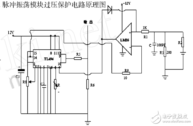
The figure above is the schematic diagram of the overvoltage protection circuit of the pulse oscillation module. This circuit is an overvoltage protection circuit that outputs 25000V in the specific experiment. When the adjustable voltage is 30V, the sampling voltage is 6V, which is greater than the reference voltage of 5V, LM358. The output will output a high level control pin 4 of the TL494, causing the TL494 to stop working.
to sum upWhen the output voltage of the DC power supply is greater than 25V, the sampling voltage is greater than 5V at this time; output a high level at the output end of the LM358 and then control the 4 feet of the TL494, so that the TL494 stops outputting the pulse outward, and the LED emits light.
ZGAR LEA BOX Vape
ZGAR electronic cigarette uses high-tech R&D, food grade disposable pod device and high-quality raw material. All package designs are Original IP. Our designer team is from Hong Kong. We have very high requirements for product quality, flavors taste and packaging design. The E-liquid is imported, materials are food grade, and assembly plant is medical-grade dust-free workshops.
Our products include disposable e-cigarettes, rechargeable e-cigarettes, rechargreable disposable vape pen, and various of flavors of cigarette cartridges. From 600puffs to 5000puffs, ZGAR bar Disposable offer high-tech R&D, E-cigarette improves battery capacity, We offer various of flavors and support customization. And printing designs can be customized. We have our own professional team and competitive quotations for any OEM or ODM works.
We supply OEM rechargeable disposable vape pen,OEM disposable electronic cigarette,ODM disposable vape pen,ODM disposable electronic cigarette,OEM/ODM vape pen e-cigarette,OEM/ODM atomizer device.


Disposable E-cigarette, ODM disposable electronic cigarette, vape pen atomizer , Device E-cig, OEM disposable electronic cigarette
ZGAR INTERNATIONAL TRADING CO., LTD. , https://www.zgarvapor.com