The UBA2028 is a compact fluorescent (CFL) electronic ballast control and high-voltage power IC developed by NXP Semiconductors. This advanced chip integrates the same control circuit as the UBA2014, along with two half-bridge power MOSFETs, making it a complete solution for dimmable CFL applications. It supports pre-heating, ignition, and dimming functions while providing system protection, making it ideal for 5–25W dimmable CFL designs.
Basic Structure and Pin Functions
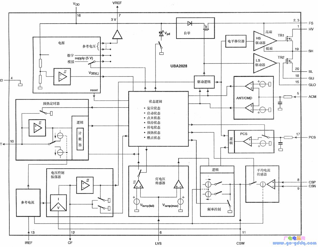
Available in a S020 package with a body width of only 7.5mm, the UBA2028 offers a compact design suitable for space-constrained applications. The top view of the pins is shown below, and its internal structure consists of a ballast controller (UBA2014) and two N-channel power MOSFETs (TR1 and TR2). A block diagram is also provided to illustrate the internal architecture.
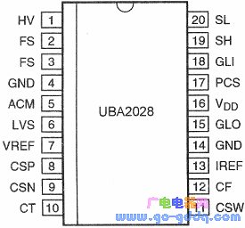
| Pin | Symbol | Features |
| 1 | HV | High voltage input |
| 2 | FS | High-end switch floating power supply |
| 3 | FS | High-end switch floating power supply |
| 4 | GND | Ground |
| 5 | ACM | Capacitive mode input |
| 6 | LVS | Lamp voltage sensing input |
| 7 | VREF | Reference voltage output |
| 8 | CSP | Average current sensor positive input |
| 9 | CSN | Average current sensor negative input |
| 10 | CT | Filament warm-up timer output |
| 11 | CSW | Voltage controlled oscillator (VCO) output |
| 12 | CF | Voltage controlled oscillator (VCO) input |
| 13 | IREF | Internal reference current input |
| 14 | GND | Ground |
| 15 | GL | Low-side MOSFET gate driver output |
| 16 | VDD | Low voltage power supply |
| 17 | PCS | Preheat current sensor input |
| 18 | GLI | Low-side MOSFET gate input |
| 19 | SH | High-side MOSFET source |
| 20 | SL | Low-side MOSFET source |
Main Features and Working Principle
The UBA2028 integrates the UBA2014 controller with two N-channel power MOSFETs rated at 600V and ≤3Ω on-resistance. It supports a steady-state current of 280mA and an ignition current of up to 1.5A. Key features include adjustable filament warm-up time, preheating current, and protection against lamp failure, open lamps, and capacitive mode operation. It is ideal for driving 5–25W dimmable CFLs.
Function and Working Principle
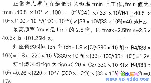
1. Startup and Oscillation: Upon power-on, the DC high voltage charges the external capacitor through the startup resistor. When the VDD pin reaches 13V, the IC starts oscillating. The internal VCO generates a sawtooth waveform, which determines the switching frequency based on the CF pin’s external capacitor, IREF resistor, and CSW voltage.
2. Timing Circuit: The timing circuit includes a clock generator and counter for preheating and ignition. During preheating, the frequency decreases until the preheat voltage is detected. Once detected, the frequency increases, and the warm-up time is determined by the external CCT capacitor and RIREF resistor.
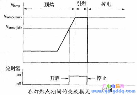
3. Ignition: After preheating, the frequency scans to the normal ignition frequency. When resonance occurs, the lamp voltage rises enough to trigger ignition. The ignition timer activates if the lamp voltage exceeds Vlamp(fail).
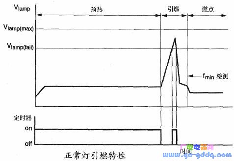
4. Lamp Failure Mode: If the lamp fails during ignition or operation, the circuit stops oscillating and enters power-down mode. This protects the system from damage and ensures safe operation.
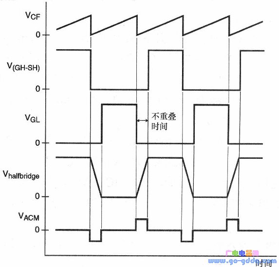
5. Capacitive Mode Protection: The ACM pin monitors the half-bridge switching characteristics. If the voltage exceeds the detection threshold during dead time, the frequency increases to avoid hard switching and protect the MOSFETs.
Application Circuit Example

This application circuit demonstrates a 20W CFL ballast using the UBA2028. Components such as R1, C11, L1, and D1 form the input filter and rectification stage. The charge pump circuit (D2, D16, Cin) improves power factor and provides protection during dimming. The filaments are heated via the choke windings, and the average current sensing circuit (C30, R18) ensures stable lamp operation.
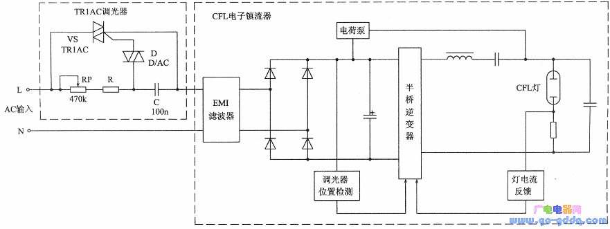
Dimming can be achieved by connecting a triac dimmer to the input. The dimmer state detector circuit (R20, R9, R21, C28, etc.) feeds the detection signal into the CSP pin, allowing the UBA2028 to adjust the lamp brightness accordingly.
Photovoltaic Single-Axis Tracking Bracket
Photovoltaic Single-Axis Tracking Bracket,One Axis Solar Tracker Solar,Solar Tracker Solar Racking Tracker,Solar Racking Tracker System Single-Axis
Hebei Shuobiao New Energy Technology Co., Ltd. , https://www.pvbracketsystem.com