Before proceeding with the setup, ensure that the connection cable is properly connected and compatible.
Start the matching process.
First, while booting the system, press and hold the previous page button simultaneously.

Second, wait for 15 seconds after the interface starts loading. Navigate to "Select > Enter 3" to proceed.

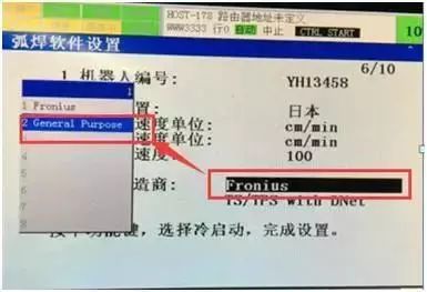
Third, after 15 seconds, you should see the settings menu. Set the manufacturer to "Fronius" under the "General Purpose" option. Sometimes, the manufacturer might already be set to Fronius, so make sure to change it back to General Purpose and then re-select Fronius.
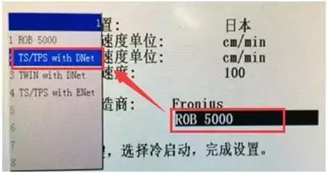
Fourth, set the type to "TS/TPS with Dnet." Ensure that a cold boot is performed before starting the system normally.
Fifth, after booting up, the following interface will appear. Enter the Device MAC ID: input "2" for both fields.
Reset IO, and select "No" when prompted.
Sixth, set the DeviceNet board to the "ON" state.
Seventh, configure the arc welding software to handle multiple welding conditions by enabling the feature.
Eighth, set the digital output signals as follows:
- (DO121): Usually used for "Weld Start"
- (DO122): Used for "Robot Ready"
Once all these settings are completed, verify the wire feeding using the teach pendant. If everything is correct, the wire should match successfully and display "OK."
After the matching process is complete, you may encounter some common issues:
1. **Alarm information: "ARC-025 is activated after welding"**
- This usually occurs after the welding process.
- To resolve this, go to the variable settings:
- Go to "AWEPCR → AWEPCR → T → AE-CHK → DI → FALSE"
2. **Motherboard not found**
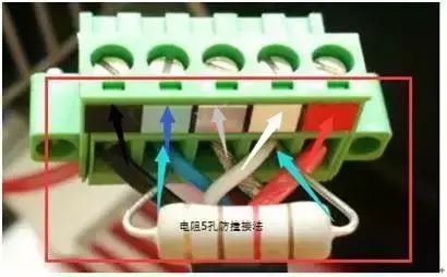
- Check the DeviceNet plug wiring. The correct order from top to bottom is:
- 1: Red
- 2: White
- 3: Silver
- 4: Blue
- 5: Black
- For the five-hole anti-collision method, connect a 120Ω resistor between the white and blue wires.
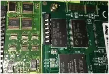
The motherboard should look like the image shown, and the DeviceNet cable should be correctly connected as indicated.
By following these steps carefully, you can ensure a smooth and accurate setup of the welding system. Always double-check connections and settings to avoid errors during operation.
Silicone Glass Fiber Tube,Pre Insulated Tube,Braided Shield Sleeve,Wire Shielding Sleeve
Shenzhen Huiyunhai Tech.Co., Ltd. , https://www.cablesleevefactory.com