Semi-blind channel estimation based on subspace decomposition in OFDM
Orthogonal Frequency Division Multiplexing (OFDM) has attracted much attention because of its good resistance to frequency selective fading and high spectrum utilization. The channel estimation technology in the OFDM system will become one of the key technologies of the fourth generation mobile communication system. The wireless channel has a complex and changeable harsh transmission environment. In order to improve the effectiveness of data transmission and reduce system errors, it is necessary to fully understand the characteristics of the channel and study more accurate channel estimation techniques.
The traditional channel estimation method is to insert pilots in the transmitted data. In order to obtain better channel estimation accuracy, more pilots must be inserted, thus greatly reducing the frequency band utilization of the system. Therefore, it is considered to apply the blind channel estimation method to the OFDM system to improve the system's frequency band utilization. Blind channel estimation does not require the insertion of pilots, but there are generally shortcomings such as low estimation accuracy, large amount of calculation, slow convergence speed, and poor flexibility. Its application in real-time systems is limited. The semi-blind channel estimation not only overcomes the shortcomings such as low precision and slow convergence speed of the blind channel estimation, but also the channel estimation accuracy under the same pilot number is better than that of the non-blind channel estimation. The semi-blind channel estimation based on the subspace decomposition method introduced in this paper utilizes the second-order statistical characteristics of the received signal without changing the OFDM system structure, which can greatly improve the channel estimation accuracy.
1 OFDM system model
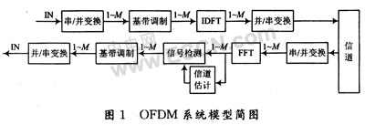
A typical OFDM system is shown in Figure 1. After serial / parallel conversion, the serial data is converted into M parallel data streams. Each data stream modulates different subcarriers. The interval between adjacent subcarriers is 1 / T. T is the duration of parallel data, which is M times that of serial data. An OFDM signal within the time interval [nT, (n + 1) T] can be expressed as: 
Where: am (m) is the symbol mapped by the constellation; ωm is the frequency of the m-th subcarrier. Sampling M points of s (t), we can get: ![]()
It can be seen from equation (2) that M samples are actually IDFT of a block composed of M inputs. In order to eliminate the inter-symbol interference (ISI) caused by multipath channels, it is different from the traditional channel estimation that inserts a guard interval longer than the channel delay, and is also different from the blind channel estimation. The semi-blind channel estimation designed in this paper inserts a small number of cyclic prefixes. Eliminate ISI.
If the length L of the channel impulse response is known, the symbols are synchronized and the frequency offset has been corrected, then, when P ≥ L, the M points of the received signal after cyclic prefix (CP) sampling are: ![]()
Where: H (·) is the frequency domain response of the channel; vi (n) is Gaussian white noise. It can be found that the ISI has been completely eliminated, and the impact of the channel on the receiver at this time is only a complex gain and Gaussian white noise.
2 Subspace decomposition algorithm
Assuming that the transmitted signal vector S and the noise vector e are generalized stationary processes and are statistically independent of each other, the transmitted signal S has a mean value of zero, the noise vector is a mean value of zero, and Gaussian white noise with a variance of σ2, the autocorrelation matrix of the received signal is: 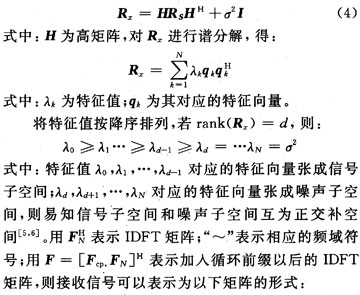
In the formula: H0 is a (N + p) × (N + p) Toeplitz matrix, H1 is a (N + p) × (N + p) upper triangular matrix. It can be seen from equation (5) that the autocorrelation covariance matrix of the received signal does not conform to the structure of subspace decomposition after the cyclic prefix is ​​added. In order to use the characteristics of subspace decomposition, starting from the original signal vector, construct a new signal vector, divide the signal into three parts of length p, Np, p, construct a new receiving vector, and make: 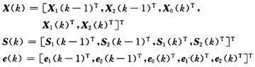
Substituting into (5), we get: 
, The autocorrelation matrix of the received signal can be written in the form of equation (5). Let gk be a eigenvector of the noise subspace, according to the nature of the subspace: 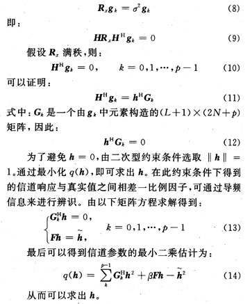
3 Simulation and result analysis
The simulation parameters are set as follows: OFDM system uses the HIPERLAN / 2 standard, the number of subcarriers is 64, the pilot interval is 7 kHz, the cyclic prefix length is 16, the number of OFDM symbols per frame is 12, the sampling period is 1 μs, the channel model It is a Rayleigh fading channel with Doppler frequency shift, in which the multipath number is 6, which is set randomly; the pilot frequency added in the semi-blind channel estimation method is 4, which is compared with the traditional channel estimation algorithm and blind channel estimation algorithm respectively The simulation curve is shown in Figure 2 and Figure 3. 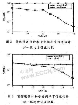
It can be drawn from the Matlab simulation curve that compared to the traditional channel estimation algorithm and blind channel estimation algorithm, the semi-blind channel estimation algorithm based on subspace decomposition can greatly reduce the channel normalized mean square error, especially when the SNR is greater than At 20 dB, the method introduced in this paper can significantly reduce the estimation error of the system, which has certain reference significance for the further study of channel estimation.
4 Conclusion
The semi-blind channel estimation method based on subspace is introduced. Simulation research is conducted comparing traditional channel estimation and blind channel estimation methods, and the advantages of subspace method in reducing system error are analyzed. How to apply theoretical research to actual systems (such as DSP systems, etc.) is the next step that is worth discussing in depth.
IEC filters are specially designed for standard IEC connectors, easy to assemble, high cost effective;
FT110I /FT110I-A/FT110I-B/FT110I-C/FT110I-D series are general purpose one-stage common mode IEC plug filters.
FT120I series are designed as two-stage high performance IEC inlet filters;
Excellent common and differential mode attenuation performance for interference from 150KHz to 30MHz;
IEC power line filters of 15A (and above) with higher parameter design, better filtering effect, especially suitable for UPS.
Optional one or two φ5.0 x 20 F type glass fuses.
Single and double-pole switches are available.


Power Line Filters Single Phase,IEC Filter,IEC Plug Filter,IEC Inlet Filter
Jinan Filtemc Electronic Equipment Co., Ltd. , https://www.chinaemifilter.com