introduction
At present, large bases (such as warehouses) are very concerned about the temperature and humidity parameters in their spaces, because it is directly related to whether the equipment stored in them can be preserved without corrosion and intact. Therefore, it is necessary to be able to automatically measure the temperature and humidity in the space and turn on the fan when needed to control the temperature and humidity. This paper proposes to use a distributed system combined with Modbus protocol to collect data with high stability and high reliability. At the same time, the powerful functions of ACCESS are used on the PC to analyze and process the data and issue fan commands, so as to realize automatic measurement and control of temperature and humidity.
1 System configuration
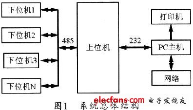
The temperature and humidity measurement and control system belongs to the sensor space three-dimensional distributed measurement and control system. It uses a PC host, an upper computer, and several lower computers to achieve master-slave communication. At the same time, it uses RS485 communication and Modbus protocol to form industrial grade 485. Network, and then add fans, printers, etc. Thus, a complete system is formed to monitor and control the temperature and humidity parameters of the base. The lower computer adopts the one-wire bus (12wireinter2face) temperature sensor to collect the temperature and humidity signals accurately with the shtll humidity sensor, and uses the PIC16 microcontroller to send the processed signal to the upper computer through the RS-485 bus. The host computer is the central control unit using AT89S52, which can perform data processing and data storage, and can realize data interaction with the PC, and then drive the on and off of the fan control switch through the network. Figure 1 shows the overall block diagram of the system.
2 Modbus protocol
Modbus protocol is suitable for half-duplex RS-485 bus. There can be a master and multiple slaves on the bus, each slave is assigned a unique address. Adopt command-response communication mode at work. Each command frame corresponds to a response frame. The host can send a command frame to the slave to be accessed, and then the slave with the matching address will respond, and then send to the host. Response frame corresponding to the command frame; slaves whose addresses do not match do not respond to the command frame. This question-and-answer communication method can greatly improve the accuracy of data transmission.
The standard Modbus protocol defines many function codes for the command frame. Different function codes require the slave to respond differently. Modbus protocol is divided into ASC code mode and RTU mode. Generally, all applications hope to expand the data transmission volume as much as possible in a relatively short time. Therefore, most of them adopt RTU mode.
Regardless of whether it is a command frame or a response frame, the start and end of the message frame must be marked with a pause of at least 3.5 character times. In the command frame, the slave address indicates which slave device on the bus received the command frame. The function code indicates what kind of response the master wants to make from the slave. The starting address of the register mainly tells the slave that the host wants to read the starting address of the internal register of the slave. The number of registers refers to how many registers the host must read from this address. The CRC check is a check code that performs CRC-16 check on all bytes of the frame starting from the slave address. The error correction ability of CRC check is extremely strong, and its application makes the accuracy rate of data transmission up to 94%. In the response frame, the slave address, function code, and CRC check have the same meaning as in the command frame. The number of bytes is the number of bytes of internal register data sent by the slave at the request of the host. Registers 1, 2, ... n are the contents of each register sent.
3 System hardware implementation
The system hardware uses a host computer and a number of lower computers to form a communication network to complete data collection and storage.
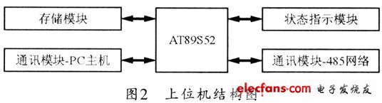
The host computer is mainly composed of AT89S52 single-chip microcomputer, communication module, storage module, and status indication module. Figure 2 shows the structure of its host computer.
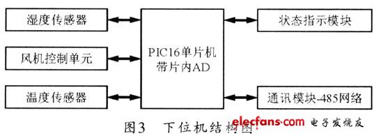
The lower computer is mainly composed of PIC16 microcontroller, temperature sensor, humidity sensor, fan control unit, status indication module and communication module. Its structure is shown in Figure 3.
Automatic Gas Cooker,Natural Fire Stove,Mini Cooker,Wifi Control Cooker Stove
JOYOUNG COMPANY LIMITED , https://www.globaljoyoung.com