Energy measurement is an important link in the modern power marketing system. The traditional electricity settlement is relying on manual to copy data to the site regularly, there are many deficiencies in real-time, accuracy and applicability; the combination of modern communication technology and computer technology and electrical energy measurement technology can be timely , Accurately and comprehensively reflect the use of electricity (ie sales). This solution first uses short-distance wireless communication to collect the electricity information of the user's electricity meter, and then sends this information to the general control center in a short message through GPRS wireless local area network to realize the remote automatic wireless meter reading function.
1 Overall system design
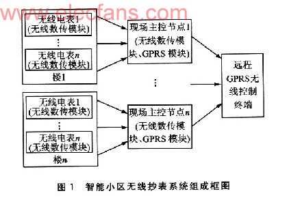
The smart meter wireless meter reading system based on GPRS is mainly composed of three parts: radio meter, on-site master control node and remote GPRS wireless control terminal. Figure 1 is a block diagram of the wireless meter reading system of a cell. The radio meter is to process the electric power collected by the traditional electric meter accordingly, and configure the wireless transceiver module to send the electric power information in a short-distance wireless manner. In addition to the wireless data transmission module, the on-site master control node also needs to configure the GPRS wireless transceiver module. First, the electricity data collected by each floor wirelessly is collected, and then the information is sent out through the GPRS module. The remote GPRS wireless control terminal mainly completes the sending and receiving of GPRS wireless data, so as to process the electricity data collected on the spot accordingly.
2 On-site main control node design
The most important thing in the wireless meter reading system is the design of the on-site master control node. This part mainly includes wireless data receiving / transmitting and GPRS data receiving / transmitting. The module used in the wireless data transceiver system is the same as the module used in the radio table. The on-site main control node is set at the center of each floor of the cell and is responsible for the initial concentration of the strain data measured at the collection point of a single unit at regular intervals. The main control node completes the signaling control and data extraction of the on-site collection point through the wireless data transmission module, and responds to the data request of the remote main control center through the GPRS module. The block diagram of the site master control node is shown in Figure 2.
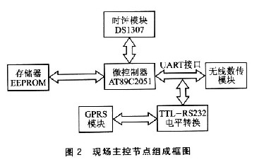
The master station uses Armel's AT89C2051 as the main controller, including wireless data transmission module, storage module, level conversion module and clock module. The microcontroller selects ATB9C2051. There is a full-duplex asynchronous serial communication module UART inside the controller, which can send / receive 8-bit data, with frame error detection function. The data memory selects the EEPROM memory AT24C256 with a capacity of 64 KB, and the SDA pin of the memory is connected to the I / O port (P1.2 pin) of the microcontroller to realize data reading / writing; Read / write timing signal. The microcontroller connects to the sending and receiving unit of the wireless data transmission module through the serial interface TX (P3.0 pin) and RX (P3.1 pin), and connects to the RS232 port of the GPRS module through the MAX232 level conversion chip. The serial port of the single-chip microcomputer is connected to the serial ports of two devices at the same time, which is prone to hardware conflicts. The time-division multiplexing method can ensure that only one serial port of a device is connected at a time.
The clock module uses the clock chip DS1307 based on the I2C bus structure. DSl307 serial real-time clock chip is a low power consumption, all using BCD code clock / calendar chip, with 56 bytes of NVSRAM. The address and data are transmitted serially through the I2C bus. It can provide seconds, minutes, hours, day, week, month and year information. It has a programmable square wave output signal; the clock can work in 24-hour mode or use AM / PM to instruct to work in 12-hour mode. DS1307 has a built-in power supply sensitive circuit, which can detect the main power failure and automatically switch to battery power supply; the optional industrial temperature is a 40 ~ +85 ℃. The microcontroller simulates the read / write control sequence of the I2C bus to complete the read / write operation of the real-time clock information.
2.1 Design of data receiving / transmitting module based on DTD462A
DTD462A is a micropower intelligent wireless data transmission module, which integrates 8-bit CMOS low-power high-speed MCU AT90S2313. DTD462A has a maximum transmit power of 10mW and works in the 433MHz ISM frequency band. It adopts FSK-based modulation and efficient forward error correction channel coding technology. It has high data resistance to burst interference and random interference, and the reliable transmission distance can reach 300m; provides transparent data interface, can adapt to any standard or non-standard user agreement; has the function of hibernation, high reliability, small size and light weight. The system uses DTD462A-96, the communication interface rate is 9600bps, the communication channel is half-duplex, and it is most suitable for point-to-multipoint communication.
DTD462 wireless data transmission module provides standard RS232, RS485 and UART / TTL level 3 interface methods, which can be directly connected to computer, RS485 device, single chip or other UART devices. DTD462 provides a 9-pin connector (JPl), its definition and connection method with the terminal are listed in Table 1.
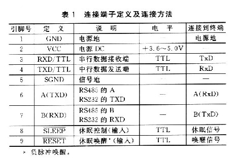
Figure 3 shows the interface design method of DTD462A and AT89C2051.

The 8th pin SLP (SLEEEP) of the DTD462A data transmission module is the sleep control signal. In order to further reduce the system power consumption, the DTD462A module of the software control field data collection node usually works in the intermittent sleep state. SLP (SLEEP) signal lasts for 1ms low level (200μs above 4800 bps), DTD462A goes to sleep. If the DTD462A is receiving air data or transmitting the received serial data to the air when the sleep signal arrives, the DTD462A will only enter the body sleep state after receiving the data. Pin 9 RST (RESET) is the external reset signal of the MCU of the micropower data transmission module. This signal is used to reset the MCU, and can also wake up the MCU that has been sleeping. This signal continues for 10μs low level, DTD462A reset or wake up. 20ms after the rising edge of the RESET signal, the DTD462A can start working.
Normally, the DTD462A module of the site master control node is in a dormant state. When it is necessary to make a data request to the collection node, the DTD462A is woken up; when the data of all the collection nodes is transmitted, the DTD462A enters the sleep state again. The on-site master control node controls the state of DTD462A through the P1.6 and P1.7 pins of AT89C2051 P1 port.
Our LED Display have high Brightness even under sunlight;Good waterproof IP65 for front and IP54 for rear,anti-corrosion,antifogging,long life span>100000Hours;The brightness of our led dsiplay is up to 6500CD, Long view distance from 100M away;The LED module is made with high quality Epistar leds keep high quality, low lighting decay, energy saving;Brightness of led display can be adjusted automatically according to different surrondings,can be set to open and close the screen on fixed automatically;LED Display can be fixed on the wall, on the street, on top of building,or be hung for rental to meet the request of live broadcast, live meeting, banquet, party, etc, to display the content what you want, by video, graphics, antimation etc, connect with PC computer or network, also can remoto control with asynchronous system;LED display Cabinet size and materials can be customized according different projects.
Key Feature:Soft mask and soft top cover design to protect player;Slope design mask to make sure wider viewing angle;0~30degree adjustable panel design;High color fidelity and uniformity;Low consumption and long lifespan;Excellent thermal management;Excellent waterproof structure;Wide viewing angle;Easy maintenance.

Perimeter Led Display,Led Display Board,Led Display Screen,Digital Display Board
Shenzhen Bako Vision Technology Co., Ltd. , http://www.rentalleddisplays.com