The control principle of the remote control circuit is to use sound to control the motion of the object. Generally, an electret microphone or a piezoelectric ceramic chip is used as a sensing element to pick up sounds, and the electronic switching action of the subsequent stage is driven by the circuit amplification. In order to prevent external audio interference, ultrasonic control can be used, but there are also deliberately used to control the audio frequency, such as using the frequency of sounds emitted by children to control voice-activated dolls, crying and so on.
The simple single-channel light control circuit utilizes the change of the internal resistance of the photosensitive tube to change the state of the electronic switch. The sensor includes a photodiode, a phototransistor, a photo-resistor, a photo-sensitive battery, etc. (early production of a glass-encapsulated transistor, After scraping off the black shading paint outside, it is a nice photocell. This light source can be either visible light or invisible light such as infrared light. Different photosensors have different spectra. Complex light control circuits are capable of multi-channel switching or analog variable control. They are extremely versatile and can be said to be available in every home. Remote control devices such as TVs with remote control, amplifiers, and VCD recorders are examples of remote control using infrared light sources. Shanghai now has many residential building corridor lights that use a combination of light control and sound control circuits to use footsteps, conversations, or other sounds from passing people to trigger the voice-activated electronic switches of lights, using light-controlled circuits. The lights automatically stop responding during the day.
The radio remote control circuit is more complicated than the voice control or light control circuit, but the control distance is also its main feature. The light control and sound control circuits are generally only a few meters to more than ten meters, while the radio remote control is used in different applications. Nearly a few meters can be, but far beyond the earth can reach space! It consists of a transmitter circuit and a receiver circuit 2 part. When the receiver receives a radio wave from the transmitter, it drives the electronic switch circuit to work. So its transmit frequency and receive frequency must be exactly the same. According to the high-frequency waveforms it launches, there are equal amplitude, amplitude modulation, frequency modulation, and digital pulse transmitters. According to the number of switches it controls, there are single-channel remote control and multi-channel remote control.
Radio remote control principle and features Equal-amplitude emission can only be used for single-channel control. The line has simple emission efficiency but very poor anti-interference. With a fixed audio frequency [/b] to modulate the [b] amplitude of the high-frequency transmitted wave (the so-called modulation is the process that causes the emitted high-frequency waves to change in response to changes in the audio frequency). The amplitude of the frequency wave changes with the change of the audio frequency. This is the amplitude modulation emission. It can use different audio frequency to control different switch channels, so it can be made into a remote control multi-channel control circuit. Since the high-frequency emission power of the amplitude modulated wave cannot be fully utilized, the high-frequency emission efficiency is relatively low, but because it employs an audio modulation method, the ability of anti-interference is greatly improved.
If a fixed frequency audio is used to modulate the frequency of the high-frequency transmitted wave such that the high frequency emission frequency produces a corresponding frequency offset with the audio frequency, this is an FM transmission. Because the FM transmitter sends a high-frequency equal-amplitude wave (high-frequency full-power transmission) and makes full use of the high-frequency transmission power, the control distance is much longer than the amplitude modulation wave when the transmitter's high-frequency transmission power is the same. Since the interference waves in nature are mostly modulated waves, the anti-jamming performance of FM waves is much better than that of amplitude modulated waves. The disadvantage is that the frequency modulation receiving circuit is more complex than the amplitude modulation receiving circuit.
If the audio used to modulate is not a fixed frequency, but directly modulates the high-frequency transmitted wave with the human voice frequency, that is radio walkie-talkie, and the basic principle of sending and receiving is the same. So, during the time I worked at the farm, I often liked to change the radio remote control circuit introduced by the relevant magazine into a simple radio walkie-talkie (at the time there were relatively few introductions to the related circuits of radio walkie-talkies.) I had a lot of fun because I was sometimes on the radio. Communication seems more interested. If digital signals are used to modulate the high-frequency emission waves, then the high-frequency pulse waves are emitted. Although the receiving electroplating is more complicated, various technical indicators have been improved, and the reliability and stability of the work are incompatible with other modulation methods.
Because the transmission power is too large to interfere with and affect the normal operation of other electronic devices (aircraft is not allowed to use the mobile phone, it is feared that the high-frequency emission wave of the mobile phone will interfere with the normal operation of the cockpit electronic equipment and cause an accident.), so each country All of them have special radio management committees to supervise and administer. They have strict restrictions and regulations on the radio wave transmission power and transmission frequency used in different situations and different work natures. For amateur radio enthusiasts, there are specialized amateur bands available for use. So when you are doing amateur radio transmission experiments, don't forget these basic common sense, so as not to cause unnecessary trouble. (If you are interested, you can look at the reference materials I attached hereto to find out about the relevant laws and regulations.).
The remote control effective distance is related to the transmitting power, receiving sensitivity and operating frequency. However, since the above-mentioned transmitting power and operating frequency are subject to various restrictions, it is generally possible to improve the receiving circuit by improving the receiving sensitivity and improving the anti-interference performance of the receiving circuit.
The most basic radio remote control circuit uses a simple super regenerative circuit to receive, and it will generate a circuit-specific noise of “sand...â€. When receiving a high-frequency equal-amplitude wave with the same frequency as the receiver, the noise is immediately suppressed. The input state of the low-frequency amplifier circuit at the rear stage is changed to drive the electronic switch operation. Since it only generates the corresponding switching signal when the transmitter is turned on or off, it can only work in the single channel remote control mode. Moreover, when the remote control distance is elongated, the circuit noise cannot be completely suppressed because the received high-frequency waves are weakened. At this time, the electronic switch is in a very unstable critical state, either on or off, which is a large remote control circuit. avoid! Therefore, the application of this remote control circuit is very small.
After the AM receiver receives the high-frequency amplitude-modulated signal after the audio modulation, the audio signal is cut off and sent to the post-stage amplifier circuit through the detection stage. If it is a multi-channel receiver, it is generally used to make precision inductors to form multi-stage LC audio filter circuits with different resonant frequencies. Each stage only allows the same audio frequency as the resonant frequency of the stage to pass through, and after processing is converted into DC level to drive behind Electronic switch. The different requirements of the receiver depending on the remote control occasions can be direct-discharge, high-level, heterodyne and other circuit combinations. The important places with high anti-interference requirements can also increase the secondary frequency conversion circuit to enhance the safety factor.
The emphasis of radio remote control circuits is on anti-interference and stability issues, so many additional circuits may be set up for safety in the circuit. After all, the radio remote control circuit and the radio are different in terms of safety requirements. The radio cannot hear the words clearly and can ask the other party to say it again. If it is wrong, it can be corrected. If the remote control used for important occasions is wrong, it may be human life. The consequences of off days!
The receiving process and principle of the digital receiving circuit I will not describe it in detail here. (The color TV remote controller uses the digital signal internally compiled by the IC to modulate the output of the infrared emitting tube and achieves multi-channel control.) Because of digital reception There is no bulky magnetic tank inductance and other components in the circuit, which can be made smaller by integration. Nowadays, the receiving circuit of the toy remote control car has used IC integrated components, which greatly improves the remote control performance and reduces the cost of production, debugging and components.
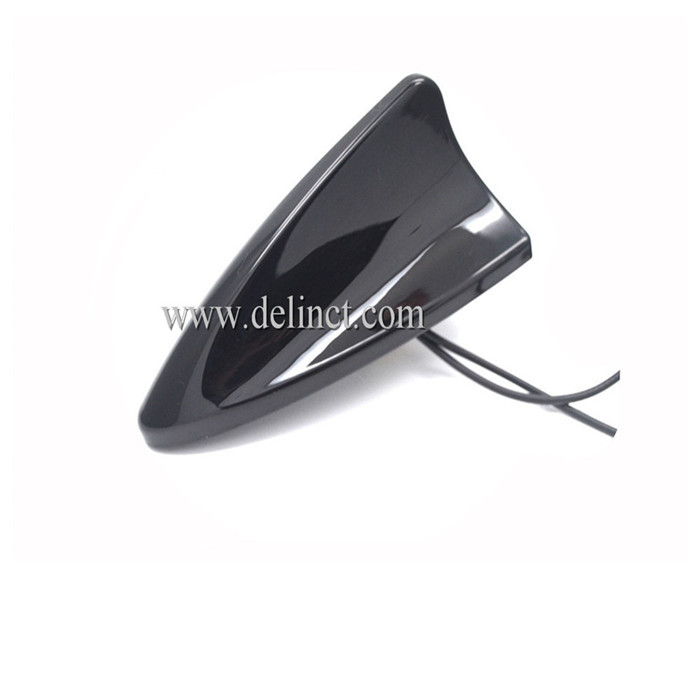
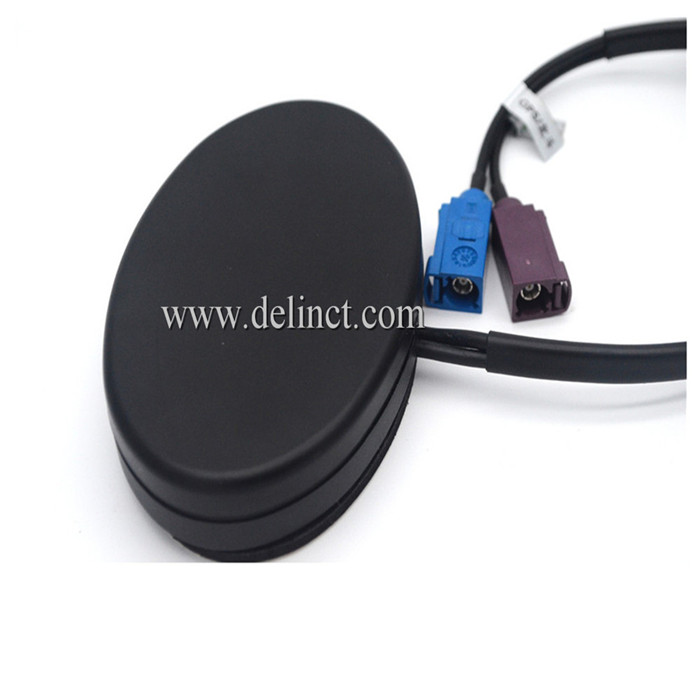
GPS / 4G / WIFI Combined Antenna set GPS / 4G / WIFI in one super antenna.
GPS Antenna is to receive GPS satellite signal, a full range of environmentally friendly materials, in line with ROSH, SGS and other international standards. The internal devices all use the international line Brand, the design of the program using bipolar tube and filter. This GPS antenna with high gain, low power consumption, strong anti-interference features;
4G is the abbreviationthe of the fourth generation of mobile communication and technology. it sets 3G and WLAN in one and is able to transmit high-quality video images which is nearly the same quality with high-definition TV . Its frequency range TDD-LTE: 2320-2370, 2570-2620MHz;
WIFI antenna is mainly to enhance the wireless network signal. But also divided into external and internal two categories: external WIFI antenna is general for wireless routers, internal WIFI antenna is mainly for mobile phones, laptops and so on. Besides, built-in wifi antenna is also divided into two categories: one is non-standard antenna, the other is standard antenna.
The shell structure of GPS / 4G / WIFI Combined Antenna uses ultrasonic design, this design of a good seal with a strong waterproof performance. Fittings all undergo a rigorous salt spray test and pull force test; GPS / 4G / WIFI Combined antenna products can withstand 85 degrees high temperature and negative 45 degrees low temperature harsh environment.


WIFI Combined Antenna,4G Combined Antenna, GPS Combined Antenna,Combined Antenna
Shenzhen DELIN Communication Technology Co., Ltd. , http://www.delinct.com