New Thinking of Automobile Power Supply Design Caused by Overload of Electrical Accessories
With the explosive growth of automotive electronic functions, will increasingly luxurious cars endanger passenger safety? This is the origin of the car's over-electrification problem. What steps should design engineers take to avoid potential dangers?
Recalling the past (not so far away), driving your dad's classic car, AM / FM radio, tape recorder and car air conditioner marked the highest level of luxury cars in that era. Today, many people can hardly imagine that the whole family ’s road trip is almost equipped with satellite navigation GPS, a separate DVD player for each passenger, in-car climate control, heated seats, cruise control, wireless access, and driver reminder. The voice prompt function with the lights always on, the engine must continue to supply power to these electronic systems, otherwise, these devices on the car will become flashy furnishings.
With the increase in automotive electronics and electrical accessories, how can manufacturers provide enough power to meet their requirements? What happens once a voltage surge or dip occurs? Will more luxurious cars endanger the safety of passengers? What solutions are needed to ensure that a highly electrified car maintains sufficient power?
Accessories power consumption shows an upward trend
Automotive electronics and electrical equipment are increasing at an average annual rate of more than 110W per car. Recently, systems that were driven by mechanical force and hydraulic pressure have been driven by electricity in the past, and most of the demand for electrical energy originates from this. The anti-lock brake system (ABS) that appeared in the 1980s has an electronic control unit with a storage capacity of about 8KB; while the modern fifth-generation ABS hardware is equipped with 128KB of memory, which is only 40% of the size of the earlier system. Due to the ingenious design and innovation, the power requirements of modern electrical / electronic systems are usually smaller than those originally introduced.
The following table summarizes the main subsystems (and loads) of Hyundai ’s automotive electrical / electronic systems:
Engine management
Multimedia and heating, ventilation and air conditioning (HVAC)
Body Electronics
Chassis Electronics
Lighting (external and internal)
Future system
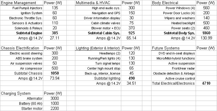
The electrical loads listed in the table are a mixture of continuous and intermittent components. However, the components of the car's electric charging system must include at least an alternator, battery, and power distribution system (that is, PowerNet). It must fully and continuously support the engine management function and most of the multimedia and HVAC functions, according to driving conditions. And consumer uses support the remaining categories of automotive electronic systems.
The two categories in the table (engine management, multimedia, and HVAC) automotive electronic systems require the automotive power system to provide 102A of current. This is very important. In order to describe the current status of the accessory overload, it should be noted that in order to support the load of 102A without adding batteries, the alternator must have about twice the rated current-204A. The reason is that when the engine is running at low speed and idling, the car alternator can only generate half of the electricity. This requires a large alternator. On a PowerNet with a nominal system voltage of 14.2V, it must provide 2,840W of power.
If the electrical loads of the remaining four subsystems are included in the car's load questionnaire with different duty cycles, it is possible to easily exceed the power supply capacity of the alternator. When this situation occurs in the current car, the voltage of PowerNet will drop until the system voltage matches the voltage of 12.8V inside the battery. At this time, the battery begins to provide part of the electrical energy for the total electrical load. This effect is called battery distribution (battery contribuTIon).
Battery allocation is a periodic event that randomly powers electrical loads that are not working regularly, such as the automatic temperature control of the passenger compartment, the event of rotating the steering wheel; or powering a deterministic load selected by the consumer, such as audio Or navigation assistant. These periodic events are the cause of battery depletion and eventually lead to the need to replace the battery.
The final point to note about this table is that if you consider the intermittent loads of subsystems such as body electronics, lighting and chassis electronics, the demand for a car charging system is really an accessory overload. Future systems will continue this trend.
Automakers are therefore taking steps to reduce the overloading of electrical systems caused by the proliferation of electronic systems. These measures include: improving the efficiency of existing electrical accessories; functional integration to eliminate duplicate control electronic systems, thereby reducing the power consumption of the control system; reducing mechanical transmission devices, for example, innovations in ABS to enable them to be smaller and lower The power consumption provides the expected function. (rewrite)
Endless power demand
The actual situation is still: In the near future, attachment overload will continue to be violent as ever, because consumers need more and more new features and functions. From the figure below, we can see the evolution of the 4th generation automotive electronic system.
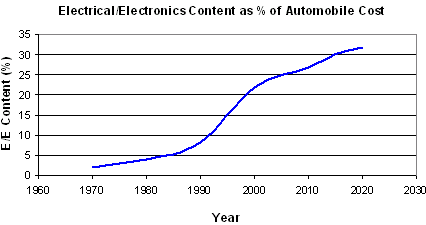
From 1968 to the 1970s, the first generation of automotive electronic systems, including electric power windows, electric door locks, air conditioners, electronic fuel injection, and electronic ignition, these systems were necessary and evolved to meet the requirements of the emissions regulations of that era. To adopt electric power steering.
From the 1980s to the early 1990s, the second-generation automotive electronic systems included ABS, anti-theft systems, and more advanced electronic engine control systems to meet the requirements of regulations that limit exhaust emissions. The second generation of automotive electronic systems is made possible by the use of software control functions and dedicated electronic control units. For example, early engine control units (ECUs) managed fuel, closed-loop control based on sensors, and electromechanical transmissions that replaced older mechanical systems. Spark plug discharge and exhaust gas recirculation.
The third generation of automotive electronic functions is made possible by the introduction of a more powerful microprocessor, such as 80186 instead of 8080, and can handle more control functions. This led to more advanced functions, such as multiplex communications and distributed computing functions, cruise control, navigation functions, and a more automated air conditioning system, and improved gearboxes to realize the automation of human-driven transmission. More advanced airbags. In the third-generation automotive electronics era, in-vehicle entertainment systems have adopted a digital signal processor (DSP), which has improved the performance of distributed electronic system architectures and expanded the application of multiplexed communications such as controller area networks (CAN).
With higher-level distributed automotive electronic systems, it is possible to free up new space from the dashboard panel, because only the control information needs to be read. The audio system of the 1990s is an example of this trend, where the radio movement and audio amplifier stage are installed in the rear window sill area of ​​the car body, leaving only the display and switches on the dashboard panel. Similar trends have emerged in systems such as climate control in cars, navigation systems, CD changers, etc.
In the fourth-generation automotive electronic system stage, the application of microprocessors and digital signal processors in automobiles has become more popular. In these 21st century systems, each car's automotive electronic system uses more than 40 to 80 microprocessors and more than 35 to 100 motors. The new system is controlled by software and relies heavily on the availability of cheap and robust memory hardware.
The number of electronic systems in automobiles in the future may not grow as fast as in the second generation, but software systems will grow exponentially. For example, a trend currently being presented is to upgrade online diagnostics (OBD) to the next generation of OBD1 through immune system engineering. The reason for this trend is that the complexity of the current system is so high that the failure mode close to 2/3 cannot be interpreted at all, and will continue to deteriorate.
To diagnose future automotive electronic systems, online computing software will need to be expanded to perform diagnostics, because future systems will include electrified high-safety subsystems that are more than an order of magnitude greater than existing systems. These high-security subsystems are included here The electrified subsystem and more subsystems discussed. At present, Electronic Throttle Control (ETC) and Electronic Power Steering System (EPS) have been extended to Electronic Stability Program (ESP) systems to manage functions such as vehicle longitudinal motion control to Electronic Controlled Brake (ECB) systems. These subsystems become the sixth category listed in the table.
PowerNet stability
With the increase of automotive electronic systems and the burden of automotive power supply systems, how can design engineers mitigate the impact of various automotive electrical equipment? Although the average power demand of these electrical equipment continues to grow at a rate of 110W per year, in fact this is not a decimal, because we have seen that the power consumption of automotive electronic systems has overloaded the power supply system. The question is what is the "last straw" that makes the car's power supply system collapse? When will this happen?
When the behavior of the chaotic system is affected by a certain stress factor, if the growth of the stress factor is silent, it will eventually approach a collapse point or a tipping point. As the demand for automotive PowerNet increases, this is happening in automobiles. From the point of view of grid stability, this situation is not so serious because of the stabilizing effect of the car battery.
Problems caused by PowerNet instantaneous fluctuations
As mentioned above, 21st-century automotive electronic systems are highly dependent on software, so they are increasingly susceptible to PowerNet variability, and crowded and messy power distribution networks are more sensitive to instantaneous changes in power consumption. Manufacturers need to install power line filtering and larger capacitor banks in more sensitive electronic modules to solve the problems faced by the deteriorating power distribution network. In fact, all electronic modules still have different levels of noise immunity; sometimes under the combined effect of the deteriorated power distribution network and the load switch of the module itself, it may cause software failure. The reason for this confusion is that the microprocessor or some supporting logic functions are susceptible to simultaneous power line fluctuations, surges, and load drive pulses.
At present, automobile manufacturers are seeking to use supercapacitor distributed modules or local energy storage devices, which can provide smooth and stable PowerNet to the ECU-related locations. The figure below depicts a layered view of the balance between distributed electronic modules, electromechanical actuators and supercapacitor energy storage devices.
In this highly simplified description, the supercapacitor distribution module or double-layer capacitor (DLC) is close to high-energy consumption loads, such as EPS (1.2KW), electromechanical brakes (1 to 2KW) and new lighting systems (such as recent White LED headlights appear). The local distributed module supplies power to the peak load to avoid strong fluctuations in the 14V power line from the alternator and battery.
The switching of high-energy-consuming loads, such as those highlighted in the figure above, has significant interference with the automotive power distribution network—14V PowerNet. For example, in some newly proposed EPS designs, the electric power steering (EPS) system has a power requirement of 130A, with a maximum of 160A. In the past, it was assumed that EPS power demand was in the range of 85A (1.2KW) to 130A (1.8KW). If it exceeds that range, it means that PowerNet is in the worst power supply state, which may endanger the normal operation of EPS. When the engine is almost idling and the continuous load is already 27A plus 67A or 1.3KW, adding an instantaneous load of 1.2 to 1.8KW to PowerNet means that the voltage fluctuation of the power distribution system is 14.2V to 12.8V; this is also the battery potential Fluctuation range. If the voltage of the power distribution system drops by 10%, then the headlights will be dimmed and the EPS performance will be degraded, not to mention the problems caused by the transmission of PowerNet transient fluctuations to all other connected ECUs.
Load smoothing method
The first half of this article depicts the transient overload of the power of automobile accessories, which will be further explained by simulation here. In the illustrated process, it is assumed that during the operation of the electric power assist system (EPS), engine management and some climate control electronic systems are also continuously working. Suppose EPS draws 90A of electric current from the power line of the car (PowerNet) for 300ms, for example, making a lane change on a hard road or parking in a parking lot at a low speed.
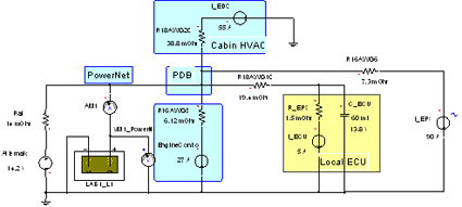
In the first case shown below, EPS is activated when PowerNet is relatively under heavy load, but the supercapacitor power distribution module is not installed. The connected load represents 27A engine management, 55A climate control and 15A remote electronic control unit (ECU). For example, the remote ECU may be an audio module, and it is intentionally shown to use local electrolytic capacitors for filtering and smoothing.

Figure: The PowerNet supplies power to the EPS in working condition, but the supercapacitor distribution module is not installed.
In the picture above, the car charging system is represented by an alternator and a lead-acid battery. In this case, it is necessary to use the Simploler electrochemical modeling tool in Ansoft's car toolbox to conduct a more detailed modeling of the battery. PowerNet is highly simplified to four branch circuits modeled by wire gauge resistance, including engine control, cabin climate control, local ECU and EPS (far right). PowerNet distribution points are marked as PDBs or power distribution boxes.
When EPS is working, the following figure depicts the PowerNet transient fluctuation caused by the above circuit. Note: When the power distribution network is stable, the initial charging current provided by the alternator to the battery.
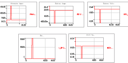
Figure: When EPS is activated, it causes PowerNet transient fluctuations
In the graph above, from left to right and top to bottom are: alternator output current, battery current, battery voltage, EPS current and local ECU terminal voltage. Note that before EPS is activated instantaneously, the battery requires a continuous charging current of 20A. In this simulation, it is assumed that the battery charge state is low and needs to be charged. The key point is the high variability of the ECU terminal voltage: 13.8V to 13.2V, then to 12.2V, and then back to 13.2V. This is a very destructive transient voltage fluctuation, whose fluctuation range exceeds the smoothing ability of large electrolytic filter capacitors.
Many such transient fluctuations will occur on the automotive power distribution network, so that the automotive power environment is full of such noise, so that various ECUs are affected by a wide range of fluctuations on the power line.
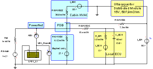
Figure: This PowerNet circuit supplies power to the activated EPS and contains a supercapacitor distributed module (top right)
The above picture is the same as the previous PowerNet circuit diagram, but a super distributed module placed at the EPS load point is added. This super module is a standard automotive design product that provides stable and smooth PowerNet like a battery near a large electrical load. As in all other places, where there is a super distributed module, a smoothing effect can be easily observed on the PowerNet and ECU voltages.
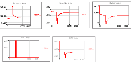
Figure: When EPS is activated, the supercapacitor distributed module smoothes the power supply fluctuations on PowerNet
As can be seen in the figure above, PowerNet equipped with supercapacitor distributed modules shows much better response behavior. Note: The displayed scale has changed, and the range of power supply change is much smaller than when the supercapacitor module is not used. The important point is that the EPS current does not change, so its function remains the same. The outstanding feature of the supercapacitor distributed module is that it greatly reduces the power line interference (lower right trace) on the terminal voltage of another branch circuit of PowerNet that supplies local ECUs.
The advantage of distributed modules or local energy storage based on carbon supercapacitor technology is that the efficiency of stabilizing PowerNet is very high, which helps smooth and stabilize the power line even in the remote branch circuit of the car.
In the not-too-distant future, automotive electronic functions and featured content will continue to grow, and with it, increasing accessories will overload the power distribution system. The large continuous power load is pushing the car charging system to overload. More and more and larger power-consuming equipment generates transient voltage fluctuations in the load, which makes the very complex and highly distributed computing network likely to be damaged.
To see this, looking at the cooling capacity of air-conditioning compressors in typical cars and air-conditioning units installed in mid-American households, you can see that the air supply motor in the car actually consumes much more electricity than the central heating system in the home. many. Many other electrical equipment in vehicles are similar. All of these electrical equipment are installed in very limited spaces, and therefore often "embracing" heat and vibration.
The supercapacitor distributed module can replace two to three lead-acid batteries to provide a power supply solution for passenger cars, and it provides sufficient filtering for the power system. In a way, it can be called an imminent tipping point. For car manufacturers, to re-arrange PowerNet and increase the voltage of the power distribution system by 3 times to reach the proposed 42V standard, a supercapacitor distributed module will be indispensable. Relying on its function alone can reduce the current of the power distribution system discussed in this article by 1/3.
In addition, in order to meet the requirements of specific functions, some transitional systems have developed in this direction, using super capacitor distributed module technology to raise the local 12V battery power supply voltage to 30V or even higher; EPS is such a function, micro-hybrid ( (Related to idle parking systems) is another example of providing higher voltages in cars.
Introduction
SCOTECH manufactures a full range of pad mounted distribution transformers, it consists of HV compartment, LV compartment and Transformer compartment, they are compact power system for utility, commercial and industrial applications. the Pad Mounted Transformer can be installed indoor or outdoor and designed to withstand most of the environments. it can also be designed specifically for the solar photovoltaic generator applications.
Scope of supply
Primary voltage up to 35KV
Rated power: up to 5MVA
Standards
SCOTECH`s pad mounted distribution transformers are designed and manufactured in accordance with all major international standards (IEC, ANSI, UL, etc.)
Why SCOTECH
Long history- Focus on transformer manufacturing since 1934.
Technical support – 134 engineers stand by for you 24/7.
Manufacturing-advanced production and testing equipment, strict QA system.
Perfect service-The complete customer service package (from quotation to energization).
Pad Mounted Transformer
Pad Transformer,Pad Mounted Transformer,3 Phase Pad Mounted Transformer,Pad Mounted Distribution Transformer
Jiangshan Scotech Electrical Co.,Ltd , https://www.scotech.com