**Detailed Explanation of New Energy Vehicle Car Charger**
Car chargers play a crucial role in the operation of new energy vehicles, and their market has grown rapidly alongside the expansion of the electric vehicle industry. In 2016, the market size for on-board car chargers was approximately 2 billion yuan. With the increasing production of new energy vehicles, it is estimated that by 2020, the domestic market for these chargers will reach 7.7 billion yuan.
Compared to traditional internal combustion engine vehicles, new energy vehicles are built around three core components: the battery system, which includes the battery and battery management system (BMS); the motor system, consisting of the motor and motor controller; and the high-voltage electric control system, which encompasses components like the on-board DC/DC converter, charger, electric air conditioner, PTC heater, and high-voltage power distribution box.
The main components within the high-voltage system are the on-board DC/DC converter and the car charger. These devices are essential for converting and managing the electrical power required by the vehicle’s systems.
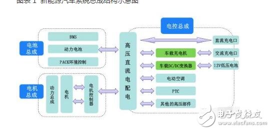
*Figure 1: Schematic diagram of the new energy vehicle system*
**Car Charger Parameters:**
1. Input voltage: AC 220V ±10%, 50-60Hz
2. Output voltage: 48V, 72V, 144V, 200-420V, 500-650V
3. Output current: 30A, 25A, 20A, 10A, 50A
4. Output power: 1.8kW, 3kW, 3.3kW, 30kW
5. Output ripple: ≤1% (full load)
6. Voltage and current stability accuracy: ≤1%
7. Harmonic distortion: ≤5%
8. Working efficiency: ≥95%
9. Working status: Supports long-term operation and single charging
10. Protection functions: Overvoltage, overcurrent, overheat, short circuit, reverse polarity protection
11. Low-voltage auxiliary power supply: DC 13.5V / 100W regulated power supply
12. CAN communication interface
13. Safety indicators: Insulation resistance ≥200MΩ, withstands 1500V/min
14. Power factor: 0.99 (with APFC)
15. Size: Varies depending on model
**Key Features:**
1. The charger supports high-speed CAN network communication with BMS to verify battery connection status and obtain real-time data from the battery system before and during charging.
2. It can communicate with the vehicle monitoring system via the CAN network, uploading working status, parameters, and fault alarms, while also receiving charging start/stop commands.
3. Comprehensive safety features include:
- AC input overvoltage protection
- AC input undervoltage alarm
- AC input overcurrent protection
- DC output overcurrent and short-circuit protection
- Soft-start function to prevent current surges
- Temperature, voltage, and current monitoring during charging
- Battery voltage limiting function based on BMS information
- Automatic detection of proper connector and cable connections
- Charging interlock to prevent vehicle startup until the charger is connected
- High-voltage interlock to stop output when unsafe conditions occur
- Flame retardant design
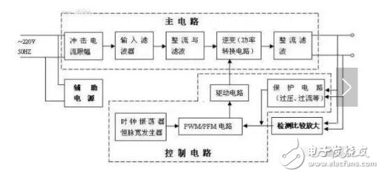
**Car Charger Diagram and Working Principle**
As a power electronic system, the car charger consists of two main parts: the power circuit and the control circuit. The power circuit typically includes a DC/DC converter made up of a transformer and power transistors, which is critical for voltage conversion.
The control circuit is centered around a controller that enables communication with the BMS and manages the charging process according to a three-stage charging curve. When the charger is connected to the AC power source, it does not immediately charge the battery. Instead, the BMS first collects and analyzes the battery's condition before adjusting the charger's parameters accordingly.
The charger is divided into two major sections: the power supply section (main circuit) and the control board. The control board handles functions such as controlling, monitoring, measuring, calculating, correcting, protecting, and communicating with external networks. It acts as the "central brain" of the charger.
The power supply section converts 220V AC to 300V DC. This part is usually split into two stages: PFC (Power Factor Correction) for AC/DC conversion and LLC for DC/DC conversion.
Outdoor Battery,Outdoor Powder Coating,Battery Rack,Integrated Rack
Guangdong Yuqiu Intelligent Technology Co.,Ltd , https://www.cntcetltd.com