Is the accuracy of the other end of the digital power device important? In fact, it is much more important than most people realize.
An example of a wrong budget
Let's use an actual IC specification and consider how precision works in it. We use a high-end FPGA. The FPGA's parameter table (below) determines the supply voltage that will ensure the IC is working properly. If the supply voltage is outside this range, the device will not be guaranteed to operate properly.
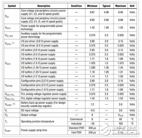
Figure 1: FPGA Specifications
Let's focus on the VCC rail, which has ±30mV fluctuations above and below the 0.85V nominal value. For a 0.85V rail, the error is ±3.5%.
At first glance, people think that ±3% POL can handle this. Unfortunately there are other considerations.

Figure 2: 10A POL load response
This oscilloscope screen capture shows a 10A load pulse on the VCC POL output. There is a ripple of about 8 mV and a brief voltage drop of 20 mV. The question is: Do these human interferences have to be within ±3.3% of the specification? The waveform in the oscilloscope plot appears at the output of the POL. We have to ask: What is the load bearing?
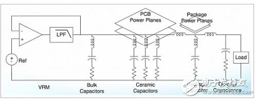
Figure 3: Power Distribution Network (PDN) Schematic
This PDN schematic, taken from DesignCon 2006 "Comparison of Power DistribuTIon Network Design Methods", shows filtering in packages and chips. PDN, package decoupling, and on-chip capacitance filter out certain high frequency parts of the transient. Therefore, the answer to the transient margin problem is: depending on the situation. In general, only the package side of the PDN will filter out the highest frequency.
Ripple is another matter. The frequency of the ripple is low, and what kind of ripple is applied to the load pins, what kind of ripple the chip will withstand. So, for our analysis, we will assume that the ripple consumes a portion of the error margin and ignores the transient.
With a ripple of 8mV, our error budget is only ±22mV, which means accuracy is about ±2.5%. Unfortunately, we have not done all the work. We must consider overvoltage (OV) and undervoltage (UV) monitors. If you look back at an article I published earlier, "Digital Power Monitoring and Telemetry," you'll see that the OV/UV monitor is the comparator that is responsible for setting the trip point and has a DAC. Our concern is the undervoltage and overvoltage accuracy.
The accuracy of the monitor is part of the error budget because we want to set the accuracy of the UV monitor above the specification and the accuracy of the OV monitor to be lower than the specification. This is the only way to ensure that the power rail meets IC power specification specifications. (Note: although we can usually add some filtering to the monitor so that the transient does not cause it to jump, the ripple will always cause it to jump.)
Now let's use the accuracy of the LTC3880 monitor, which is ±2%. On our 0.85V power rail, it is 17mV. Now, our margin is only 4mV! The POL output voltage accuracy must now be 0.5%! Can this be achieved?
The LTC3880 datasheet shows that the monitor's output accuracy is ±0.5%. Our power rails meet the specifications, and the monitors ensure that it works. In the previous article we talked about selectively triggering and shutting down if the specifications are not met, and managing the controllers to the basic board (BMC) ) Send a fault.
Review mathematics
FPGA specification: 30mV
Remove the ripple: 22mV
Remove monitor accuracy: 4mV
Remove the control loop accuracy: 0mV
Is there a compromise?
It depends on the level of quality you want. If you remove the monitor from the specification and rely on the control loop, the required control loop accuracy is 2% and the LTC3880 is 4 times better. This means that it can even support power rails below 0.85V. However, there is one last aspect that we did not consider. When you think we have done our work, there are actually more issues to deal with.
What is the situation of margin adjustment?
In a production environment, the power system operates at (or exceeds) high and low specification values ​​to eliminate any edge in the system. In our design, this means running the system with an accuracy of ±3.5%. During margin adjustment, the monitor will do a little "give way" because the goal at this point is to ensure that the system is reliable over the entire specification.
We want to ensure that we can work in extreme situations, so we need to control the accuracy of the control loop so that the power rail setting can exceed the extreme conditions to ensure extreme conditions even exceed the actual value of extreme conditions. If the control loop accuracy is 0.5%, then we should set the power rail to ±4%. If the control loop accuracy is only 2% (similar to the monitor), what happens? The value should be ±5.5%.
No big problem, right?
If the FPGA application loses timing margin due to higher margin values, then margin testing can trigger costly failures. You may need to add timing margin to the design to pass the margin test, and if you can't tolerate margins, it may lead to a drop in yield. Alternatively, you can also reduce the margin value and lower the quality (discard some defects). No matter which method you take, it is not that you are your customer. If you set the margin value correctly and correctly, it will delay the progress of the project, and you will suffer loss of yield and hurt your bottom line. And if you falsify in the margin test, your customers will suffer losses because their systems will not be reliable. Therefore, the accuracy of the control loop is indeed critical. this is a big problem.
Read product specifications
Specifications provided by the manufacturer should be treated with caution. Each manufacturer uses its unique structure when specifying its accuracy. The control loop accuracy will consist of multiple parts:
1. Voltage difference amplifier offset and gain
2. Voltage reference for the ADC
3. ADC offset and gain
4. Effects of external components (eg resistor divider)
The product manual sometimes specifies the above indicators separately, or some of them are omitted from the specifications, or the accuracy of the output is not directly specified at all. The LTC3880 specifies the “total errorâ€, so the actual accuracy is clear at a glance. When comparing devices, if the total error specification is not given in the product manual, it must always be calculated. Otherwise, if you encounter problems later in the design process (or worse, in mass production), you may regret it for your choice.
summary
We studied the FPGA specifications and made an error budget. We found other error budget components, including: ripple, control loop accuracy, monitor accuracy, and margin accuracy. Direct comparison of FPGA specifications and POL performance indicators does not reflect the overall situation. The accuracy of the POL must be significantly higher than the specifications given in the FPGA product manual to ensure that the operation of the device is within specifications and to ensure reliability across the entire specification while maintaining high yields in production.
Three-axis Smartphone Stabilizer is composed of pan axis, rolling axis and tilt-axis. With a gyro-stabilized gimbal system, it keeps stabilized or steerable horizon with automatic calibration to give you an unprecedented smooth shooting experience.

Three-Axis Smartphone Stabilizer is born for video lovers. it stabilizers the video footage horizontally, without sacrificing the thrill of dynamic motion in the video.

Wewow focusing on handheld stabilizer is a technology company which does R & D independently. With Wenpod series product released, the company achieved the industry's praise and quickly became the leader of the smart stabilizer industry.
Our service
1. Reply to you within 24 hours.
2. Already sample: within 1-2days.
3. Shipping date: within 24 hours once get the payment.
4. 12 months warranty.
5. After-sales service, solve within 3 working dates.
If you have any questions, please contact with us directly.
Wewow appreciates domestic and international business relationship!
Three-axis Smartphone Stabilizer
Three-Axis Smartphone Stabilizer,3 Axis Handheld Gimbal For Smartphone,Smartphone Gimbal For Cell Phone,Three-Axis Stabilizer For Smartphone
GUANGZHOU WEWOW ELECTRONIC CO., LTD. , https://www.stabilizers.pl