introduction
The goal of improving system-level smart grid power load management is increasing during periods of high demand or limited resource availability, which requires more efficient ways to connect the load to the grid or disconnect the load from the grid. Load management systems have been used in commercial and industrial fields for some time. However, as smart grid management systems are now entering the stage of home and commercial internal control equipment, the reliability, efficiency and cost-effectiveness of these devices become even more important.
Because the smart meter is directly connected to the power transmission and distribution of the power grid and controlled by the microcontroller, the connection/disconnection solution must have the function of withstanding the environment of the smart meter noise. The best solution is to combine the powerful DC current capability of the open contactor with the precise timing function, relay function and compatibility of the filtered noise to optimize the clock cycle of the microprocessor.
This article reviews the implementations that are currently in use and still under development. This article also describes smart grid system load management recommendations and the switches required in emerging markets. Mechanical two-coil relays were tested to define optimized driver circuits that provide the required functionality.
The paper concludes with a discussion of the power systems required to drive the connected relays and the drive tradeoffs that meet the recommended performance specifications.
Smart grid impact
The smart grid initiative has spawned a new approach to load management. The basic technology of the remote controller and the ordering of the basic form of the load have been active in the industrial market for a long time, and have been attracting various businesses. Initially, this was done primarily through a separate telephone line device connected to public power and an alerting and requesting system implemented via a telephone communication device mechanism. By introducing wireless and power line carrier (PLC) communication technologies and a healthy competitive mechanism, costs have been significantly reduced, resulting in ever-decreasing costs and improved performance. It does not rely on direct-attached circuit installation and intrinsic security in wireless implementations, dramatically reducing installation process cost and complexity.
Household electricity meter market
Another need for an economical connection/disconnection solution comes from the household electricity meter market. Since the timely communication with a single meter and local control functions is improved, the meter load can be turned on remotely, thereby greatly reducing the cost of simple service interruption or service recovery. When a customer requests a business interruption and reconnection, such as for a seasonal vacation and rental property, no service relay is required. It also minimizes the problem of no bill payment when trading in personal business. Similar savings methods are also available for temporary construction sites and other venues that do not require continuous use of the business. Remote management capabilities also reduce theft of unused sites and circumvent related power losses.
Avoiding meter socket failure
Recently, the installation of a smart meter around an old meter socket caused a fire, causing concern. When replacing an old meter that has been in use for a long time, the problem tracking shows that the meter socket is getting hot due to contactor corrosion in the meter. Socket heating is the result of a combination of load current and corrosion, mainly caused by weather damage and water seepage. Disconnecting the load and reporting an overtemperature condition helps the meter to be safe from damage.
Disconnect after losing power
Increasing the importance of contactors is the ability to disconnect and reconnect after losing power. This is especially important when controlling equipment such as compressors that have high starting surge currents and that are preferably not cycled when there is no minimum turn-off cycle (the compressor produces excessive heat when cycled in short cycles). By delaying the turn-on time and sequencing the load, the power recovery surge current can be reduced, thereby reducing peak inrush current and stress on the transmission equipment and load. Contactors based on electricity meters and loads can provide this function with a capacitor that stores the power to maintain the power to apply a pulse to open the contactor even in the event of power loss. Smart grid research shows significant advantages in device reliability and stability when using these types of strategies.
Industrial market
In the industrial market, contactor functions have been implemented in a variety of ways. The motor can be used to drive the contactor, but the contactor opens very slowly due to arcing damage. For larger systems, various forms of arc suppression are typically employed, including compressed gas and spring assisted fast switching mechanisms. This is not very economical for markets that are sensitive to higher costs. Therefore, there is a growing consensus to use a polarized bistable latch relay with two coils, one coil applying a pulse to move the relay from the off position to the on position and the other coil moving the relay from the on position to the off position.
Drive configuration details
A bistable, dual coil latching relay is the most common configuration. Some versions include built-in springs and other mechanical aids in the open position for low power operation.
Typical load connection functions are achieved by a bistable contactor that is disconnected by two or more poles. The contactor is usually wound with two windings, one for closing the contactor and the other for opening the contactor. Use permanent magnet material or mechanical latches to ensure that the contactor is in place when it is not switched.
In order to facilitate mechanical movement, the relay coil needs to be energized for a certain period of time. Once the contactor has been replaced, the voltage in the relay winding should be removed. The illustration shows a simple typical circuit diagram, including waveform examples.
Relay drive circuit requirements
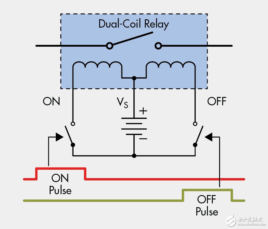
Figure 1: Simple relay drive circuit
As shown, the two-coil relay is connected to the supply voltage rail at the midpoint of the two relay windings. Each winding is energized by a switch connected to the relay coil. The two switches cannot always be on, otherwise excessive current is drawn from the supply rail, causing abnormal operation and damaging the relay. In addition, in order to accommodate the relatively long time required for the relay contactor to move between its fixed position (on/off position), the pulse must be longer than the minimum interval specified in the relay specification. In order to prevent the relay winding potential from saturating and to avoid overheating of the coil and drive electronics, it is also necessary to limit the maximum length of the drive pulse. The control signals should also be compatible with the latest generation of microprocessors that support CMOS and TTL input levels.
The relay specifications also define the maximum and minimum operating voltages required for reliable operation of the contactor. The voltage requirements of the contactor depend on the application and the application is driven by the requirements of the meter. Lower voltages are used in lower cost, lower power applications where the meters and relays are smaller. Higher voltages are used in applications where larger currents are required, with larger contactors requiring more power for switching operations. Therefore, the drive current should monitor the relay bias to ensure adequate levels. The driver circuit also requires an undervoltage lockout function to facilitate smooth start-up during circuit initialization.
The preferred integrated solution provides input qualification for control signals, prevents simultaneous activation of both relay coils, limits maximum drive pulse spacing, and provides other functions such as bias monitoring, drive enable input, and drive thermal protection. The ideal circuit minimizes component count and board space while improving system reliability and circuit noise immunity when driving relay coils.
Smd Speaker,Smd Subwoofer,Mini Smd Speaker,Smd Piezo Speaker
NINGBO SANCO ELECTRONICS CO., LTD. , https://www.sancobuzzer.com