In the CNC machine system, the functional modules can be divided into two parts: one is the function with low real-time requirements, such as human-machine interface interaction management; the other part is the function with high real-time requirements, mainly servo control and interpolation. Calculation, etc. According to this feature, the system adopts a two-level control structure, using IPC's rich software resources to provide a graphical human-computer interaction environment; using the high real-time and stability of the embedded execution controller to achieve fast and reliable control, Give full play to the advantages of both. Real-time communication is performed between the two levels using a serial port. This article focuses on the implementation of embedded execution controllers.
1 CNC machine system hardware structure
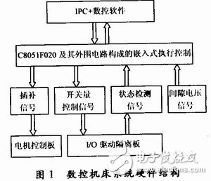
The hardware structure of CNC machine tool system is shown in Figure 1. IPC is used as the upper computer and special software is installed to realize human-computer interaction. The embedded execution controller composed of C8051020 chip and its peripheral circuits is used as the lower computer, which is responsible for real-time and reliable control. The execution controller receives the command information of the host computer through the serial port (including: interpolation command, switch quantity control command), and then converts the information into a control signal and supplies it to the corresponding executing component. For example, the interpolation command is converted into a series of interpolation signals and sent to the motor control unit; the switch quantity control command is converted into an output signal, and is sent to the corresponding switch controller through the I/O drive isolation interface board. The execution controller also has two inspection tasks: one is the detection of whether the tool moves to the limit position of each axis, and the other is the detection of the gap voltage. These two pieces of information will provide the basis for automatic adjustment control during exercise. The execution controller is also responsible for assembling the running status information into frames and transmitting them to the host computer in real time.
2 μC/OS-II transplantation on C8051F020
To use μC/OS-II, you must first successfully port this kernel to the C805lF020. The migration of μC/OS-II is mainly for OS_CPU. H, OS_CPU_A. ASM and OS_CPU_ C. C three files are modified, the following is a description of the specific changes.
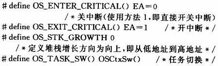
2.1 OS_CPU. H file modification
OS_CPU. H includes processor-related constants, macros, and type definitions defined with #define. Among them, the parts that need to be modified are as follows:
2.2 OS_CPU_A. ASM file modification
This file contains 4 assembly language functions.
(1) The OSStartHighRdy() function is called in the multitasking system startup function OSStart(). The function is to set the system running flag OSRunning=TRUE; load the stack pointer of the highest priority task in the ready list to the SP, and force the interrupt to return.
(2) The OSCtxSw() function is called in the task level switch function. The function is to save the environment variable of the current task, save the current SP into the task TCB, load the SP of the highest priority task, restore the environment variable of the highest priority task, and return the interrupt. This completes the task level switching.
(3) OSIntCtxSw() is called in the exit interrupt service function OSIntExit(). The role is to achieve interrupt level task switching.
(4) OSTIcklSR () system clock tick interrupt service function, the size of the cycle determines the minimum time interval service that the kernel can provide to the application system. This interrupt is completed by the TO timer of the C8051F020, and the set timing is 20 ms. Modify the code as follows:
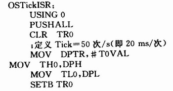
Among them: TOVAL is the time constant of 16-bit timer T0. The system uses 25 MHz external crystal oscillator and mode 1 (16-bit) timing.
2.3 OS_CPU_C. Modification of C file
The file defines 10 C functions as follows:
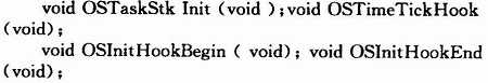
Among them, the most important is OSTaskStklnit (), its role is to initialize the stack, return the lowest address of the stack, the length of the stack, to facilitate the assembly language to achieve task switching. The other nine functions have no specific functions, and their functions can be added as needed when the system kernel is expanded.
3 Design of CNC machine tool system based on μC/OS-II
3.1 Software structure of the execution controller
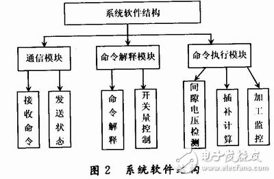
As shown in Figure 2, the system is generally divided into three functional blocks, namely: communication with IPC, command interpretation and command execution. Among them, the communication has two aspects of sending and receiving; when the command is interpreted, the switch quantity control command is directly executed; during the command execution, the interpolation calculation, the detection of the gap voltage and the limit switch state, and the processing monitoring are required.
3.2 Task division and its priority
(1) Sending a task
There are two types of information that the embedded execution controller sends to the IPC: the contact signal and the status information in the run. When the embedded execution controller is in the standby state, it periodically sends a contact signal to the IPC to determine whether the IPC is working properly. If the IPC is operating normally, the IPC will send a response signal to the embedded execution controller after receiving the contact signal. If the multiple contact signals are not received, the IPC is considered to be in error. When the embedded actuator is in the machining state, the running status information is periodically sent to the IPC in a fixed format. After receiving the information, IPC converts it into graphics, text and other information to provide to the operator, so that it is easy to grasp the processing status in real time, and the real-time requirements for sending tasks are low.
(2) Receiving tasks
The embedded execution controller receives three kinds of information: contact, response and command sent by the IPC. If the contact signal or the response signal is received, the receiving task directly processes (sends the response signal or refreshes the contact status bit); if it is neither a contact signal nor If it is not a response signal, it is considered to be command information. After the receiving task completes the command, it closes the write-receive buffer and activates the command interpretation task. The receiving task is triggered by the communication port receiving interrupt, and its real-time requirement is high.
(3) Command interpretation task
The command interpretation task first checks and interprets the command information of the receive buffer. After the processing is completed, the receive buffer is cleared and opened, and the new command is allowed to be received. The purpose of this is to not accumulate multiple commands in the receive buffer and not receive new commands until the current command is interpreted to improve the response speed of the embedded execution controller to the commands. According to the length of the command execution time, the commands are divided into two types: the switch control command and the interpolation command. The execution time of the digital control command is short, so it is executed directly after the command is interpreted to reduce the time consumption of the task switching. The interpolation command is a machining command, which runs for a long time and is executed by a special machining monitoring task. The command interpretation task is only responsible for activating the machining monitoring task after the command interpretation is completed. The command interpretation task has high real-time requirements.
(4) Processing monitoring tasks
The machining monitoring task activates the interpolation calculation task according to the current working state (manual mode or automatic mode) and monitors the machining status. In the manual mode, the operator manually controls the tool to move in the six directions of -x, +x, -y, +y, -z, +z, the tool return to the reference point, the end face alignment and the hole center positioning on the PC. In the automatic working mode, the operator transmits a linear and circular motion command to the controller, and the controller automatically completes the linear motion. The real-time requirements of processing monitoring tasks are high.
(5) Interpolation calculation task
The interpolation calculation task is to calculate the intermediate point coordinate values ​​of the start and end points of the contour. The system uses the point-by-point comparison method for interpolation. The interpolation task generates one stroke increment for each execution, and each stroke increment is output to the stepping motor by one pulse. The interpolation task may have a lower operating cycle than the operating system clock, reaching thousands of times per second, so Timer 1 is used as the interpolation motion time controller. Interpolation computing tasks have the highest real-time requirements in the software.
(6) Gap voltage detection and limit switch status detection task
The system is used for EDM CNC machine tools. The gap voltage is the discharge voltage between the tool (electrode wire) and the workpiece during EDM. This data is an important parameter for real-time detection of the EDM process and needs to be collected in real time. A limit switch is a state switch that is triggered when the tool moves to the boundary of the processing table. When the sensor switch is reached, the tool should stop working and play a protective role, which limits the displacement of the motion. This information also needs to be collected in real time. These two tasks are characterized by high real-time performance, frequent execution, and short execution time, so they are set as a detection task. As with the interpolation task, since the running period of the detection task is lower than the operating system clock, Timer 3 is used as the time trigger for detecting the task.
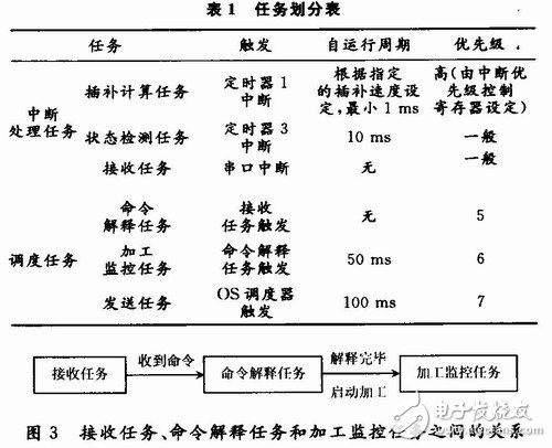
The functions implemented above are divided into six tasks, the functions of these tasks are introduced, and their real-time requirements are analyzed. The above tasks are divided as shown in Table 1.
3.3 Inter-task communication
After completing the task partitioning, you also need to consider the communication and synchronization of the tasks. The sending task and the detecting task are independent, and there is a connection between the receiving task, the command interpretation task, and the processing monitoring task. As shown in FIG. 3, the semaphore and the mailbox are used to solve the communication synchronization between the tasks.
(1) Command semaphore SemCmd. When the receiving task receives a command message, it sends out the semaphore, which is received by the command interpretation task. After the command is fetched and interpreted, the semaphore is cleared and a new command is allowed to be received.
(2) Processing start message mailbox Mbox. When the command interpretation task finds that the command information is an interpolation command, the information is translated into an agreed format and stored in the mailbox, sent out, and processed by the monitoring task.
4 Experimental results
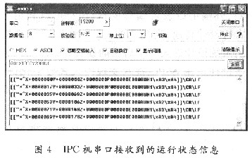
In the experimental test, the IPC sends a linear interpolation command G01X1000Y2000\LF to the execution controller through the serial port. As shown in Fig. 4, the x and y coordinate of the return information are observed, and the points are basically distributed at points (O, O) and points ( The error around the straight line of 1000, 2 000) is less than 1 motion equivalent, which means the whole system is operating normally.
5 Conclusion
C8051F020 processor has rich hardware resources and powerful processing performance. μC/OS-II has the characteristics of high real-time performance, good versatility, convenient porting and expansion. Based on the software and hardware platform, the complexity of the system can be reduced and the development speed of the product can be improved. It has been verified that the hardware and software system can meet the requirements of the numerical control system and is feasible.
Led Panel Light,Led Panel Lamp,Smart Led Panel Light,Led Ceiling Panel Light
Changxing Fanya Lighting Co.,Ltd , https://www.fyledlights.com