The use of small drones in modern military and civilian applications has become more widespread. After experiencing the early remote flight, its navigation control mode has been developed into autonomous flight and intelligent flight. The change of navigation mode puts higher requirements on the accuracy of flight control computer; with the increase of the complexity of small unmanned aerial vehicles, the operation speed of flight control computer is higher; and the requirement of miniaturization is for flight control. The power consumption and size of the computer also place high demands. High precision requires not only high computer control precision, but also the ability to run complex control algorithms. Miniaturization requires that the drone is small in size and maneuverable, and the smaller the control computer is required.
Among the many processor chips, the chip that is most suitable for the small flight control computer CPU is TI's TMS320LF2407. Its computing speed and numerous peripheral interface circuits are suitable for real-time control of small UAVs. It adopts Harvard architecture and multi-stage pipeline operation to simultaneously read data and instructions. The on-chip self-contained resources include 16 10-bit A/D converters with automatic sequencing function to ensure that up to 16 channels have conversion during the same conversion period. Perform without increasing CPU overhead; 40 channels of universal input/output channels that can be individually programmed or multiplexed; 5 external interrupts; integrated serial communication interface (SCI) for other controllers in the system The ability to perform asynchronous (RS 485) communication; the 16-bit synchronous serial peripheral interface (SPI) can be easily used to communicate with other peripheral devices; the watchdog timer module (WDT) and CAN communication module are also provided.
Flight control system
The flight control system collects the flight state data measured by each sensor in real time, and receives the control commands and data transmitted by the radio monitoring and control terminal from the uplink channel of the ground monitoring and control station. After calculation, the control command is output to the executing mechanism to realize the UAV. Control of various flight modes and management and control of mission equipment; simultaneously transmit the status data of the drone and the operational status parameters of the engine, onboard power supply system and mission equipment to the onboard radio data terminal in real time, via radio The channel is sent back to the ground station. According to the function division, the hardware of the flight control system includes: a main control module, a signal conditioning and interface module, a data acquisition module, and a servo drive module. The specific hardware structure principle is shown in Figure 1.
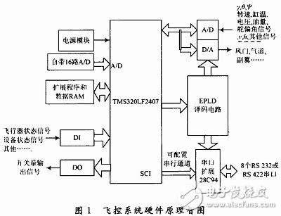
Module function
The various functional modules are combined to form the core of the flight control system, and the main control module is the core of the flight control system. It is combined with the signal conditioning module, the interface module and the servo drive module, and only needs to modify the software and simply change the peripheral circuit. Based on the requirements of a series of small UAV flight control and flight management functions, it can achieve one development, multiple models, and reduce system development costs. The system mainly completes the following functions:
(1) Complete high-precision acquisition of multi-channel analog signals, including gyro signal, heading signal, rudder angle signal, engine speed, cylinder temperature signal, dynamic and static pressure sensor signal, power supply voltage signal, etc. Due to the accuracy of the CPU's own A/D and the limited number of channels, an additional data acquisition circuit is used, the chip select and control signals are generated by the decoding circuit in the EPLD.
(2) The output switching signal, analog signal and PWM pulse signal can be adapted to the control requirements of different actuators (such as rudder, aileron servo, elevator, air passage and damper).
(3) Communication with onboard data terminals, GPS signals, digital sensors, and related task devices is realized by using a plurality of communication channels. Since the serial port configured by the CPU's own SCI channel cannot meet the system requirements, the design uses multiple serial port expansion chips 28C94 to expand 8 serial ports.
System software design
The software design of the system is divided into two parts, namely the programming of the logic circuit chip EPLD decoding circuit and the application design of the flight control system.
Logic circuit programming
EPLD is used to form a digital logic control circuit that performs decoding and isolation and provides chip select signals and read/write control signals for A/D, D/A, and 28C94. The design of the software adopts the hybrid design of schematic input and VERILOG HDL language programming, following the process of design input → design implementation → design verification → device programming. The system uses two ispLSI1048 chips, which are used to control A/D, D/A and control the serial port expansion chip 28C94.
System application design
Because C language can not only write applications, system programs, but also directly control computer hardware like assembly language, the program written is highly portable. Since the DSP-based system involves a large number of operations on peripheral ports and considers the subsequent program migration, the application of the flight control system is designed using BC 3.1 to implement flight control and flight management functions.
The software is divided into four modules according to functions: time management module, data acquisition and processing module, communication module, and control law solving module. The UAV is controlled in real time by the time management module in millisecond time; the data acquisition module collects the flight state, attitude parameters, flight parameters, flight status and flight parameters of the UAV for telemetry coding and transmits to the machine through the serial interface. The data-carrying terminal is sent to the ground control station for flight monitoring through the wireless data channel; the attitude parameter is sent to the control law solving module through the software internal interface for solution calculation, and the result is sent to the on-board servo system through the D/A channel to control the steering gear. Operation, to achieve the purpose of adjustment, aircraft flight attitude; communication module to complete the data exchange function between the flight control computer and other onboard peripherals.
Utilizing the advantages of high-speed DSP control chip in control law calculation and data processing and its rich external resources, with large-scale programmable logic device CPLD and serial interface expansion chip 28C94 design small airborne flight control computer, with its core design The small UAV flight control system has the functions of full function, small size, light weight and low power consumption, which satisfies the requirements of small UAVs for high precision, miniaturization and low cost of flight control computers. This design has been successfully applied to a verification drone system.
Earphone For Mobile Phone advantage:
Enriched sound and reliable quality in all aspects of their design,Strong bass generated from powerful driver,power and great sensitivity response,Their uniquely contoured body allow for a 45 degree in-ear angle which offers ergonomic comfort and noise isolation better than standard headphones,Stylish color design with mic and volume controller, CE and FCC marks, EN71, WEEE, ROHS AND REACH IF NEEDED
Earphone For Mobile Phone
Earphone For Mobile Phone,Plug Double Online Headphones,Bluetooth Headset,Stereo Headphone
Dongguan City Leya Electronic Technology Co. Ltd , https://www.dgleya.com