Implement isolation for communication
From the industrial control system to the roadside traffic information notice board, the RS485 network is the basis for various applications to communicate. In a high-voltage environment, from the perspective of personal safety and equipment protection, electrical isolation is often performed between the communication bus and the logic controller.
The positive impact of isolation on system performance is far from simple to protect it from dangerous voltages, but this is always ignored by people. In fact, isolation can make communication uninterrupted in the presence of severe disturbances and other system-level noise. , Error-free.
Currently there are isolated RS485 transceivers provided by different manufacturers on the market. Most of these solutions provide data isolation and do not provide the isolated power required to drive the bus interface. Users have to design their own solutions, but this requires bulky and expensive discrete components to form isolated DC / DC converters. Overall size, cost, power consumption, or complexity may discourage designers from using isolation in the system, and the system may actually benefit from isolation.
Linear Technology's new isolator miniature module (? Module) technology uses a small 11.25mm x 15mm x 2.8mm surface mount to provide a complete power and data isolation solution (Figure 1). LTM2881 contains a reliable isolated RS485 transceiver and an isolated DC-DC converter, which can provide up to 1W of power for bus interface circuits and auxiliary circuits. This micro-module transceiver requires no external components, and even decoupling capacitors and an electrically-interruptible network termination resistor are built-in. For designing and isolating the RS485 network of each communication node, the ease of use and small footprint make the LTM2881 more attractive than ever.
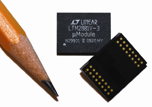
Figure 1: Linear Technology ’s new isolator micromodule LTM2881.
This article will discuss the performance benefits of using isolation in an RS485 network, point out the network characteristics that may benefit from isolation, and explain how to balance the various wiring configurations in order to maximize the performance of the isolation system.
Ground and common mode voltage interference
RS485 was developed and standardized to communicate between transceivers with a ground potential difference of up to ± 7V. Relative to the local "ground" of any node, the signal on the bus is allowed to bear a voltage of -7V to + 12V. These ground potential differences are caused by various conditions, including changes in ground potential, or voltage drops in the ground loop shared by other circuits affected by the load.
In some cases, transient events that are not directly connected may cause ground potential changes that far exceed ± 7V. These situations may introduce errors in the received data, or worse, damage the transceiver and related system circuits. Appropriate use of an isolated transceiver such as Linear Technology's LTM2881 can expand the allowed common-mode voltage range (average voltage of differential signal lines relative to ground) and protect the circuit from 560V continuous high voltage or 3750VDC for 60 seconds Damage caused. When network lines pass between buildings, indirect lightning strikes are a common cause of severe voltage interference. Transient voltage suppressors (TVS) are often used to absorb very high transient voltages, while providing additional protection with isolation. Without isolation, a single voltage surge can damage all equipment on a network.
Repeated ground and signal interference may result from coupling to the 60Hz AC power line adjacent to the RS485 bus wiring, or 60Hz current may be conducted to the common ground or power line. Computers, printers, fluorescent lamps, variable-speed motor drives and other electronic non-linear loads will also introduce significant frequency harmonics to the power distribution neutral, grounding and communication network lines. As shown below, these interferences can cause real data errors in the RS485 network, and isolation can alleviate this problem.
Send data is not accepted
The RS485 wiring configuration for non-isolated and isolated networks is shown in Figure 2. For convenience, the figure shows point-to-point one-way communication, but the concept is also applicable to multi-node networks. Figure 2a shows a non-isolated, unshielded twisted pair connection using a low-cost Category 5e (Cat 5e) cable. Figure 3 shows the oscilloscope waveform captured at multiple points on this network when driving a 100-foot cable and introducing a ground potential difference between the driver and receiver. The color of the waveform corresponds to the color of the probe position in Figure 2. All signals at the output of the receiver are measured relative to ground potential.
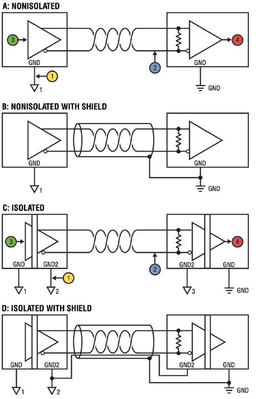
Figure 2: RS485 wiring configuration
Channel 3 (green) shows the data signal entering the transmit driver at the DI pin, and channel 4 (red) is the data output from the RO pin of the remote transceiver. This output should follow the data input, but with a transmission delay.
The yellow waveform in the upper part of Figure 3 is a sine wave voltage signal introduced between ground potentials with a magnitude of 7V (14VPP). Channel 2 (blue) shows the "B" signal at the negative input of the receiver after passing through a 100-foot cable. The digital data at the “B†terminal superimposed on the large common mode voltage signal is almost imperceptible compared to this large common mode voltage signal.
Figure 3 shows the obvious error. There are two factors that cause data loss. Both of these factors are related to the limited common-mode rejection of the RS485 receiver. First, the high-frequency component of the common-mode signal (approximately 1.2MHz here) exceeds the effective bandwidth of the common-mode rejection of most RS485 receivers; second, the amplitude of the common-mode signal provided to the receiver far exceeds the allowed -7V to + 12V range. In this case, the signal amplitude at the end of the 100-foot wire will reach a peak of ± 20V, although the peak voltage at which excitation is introduced at the near end is only ± 7V. This amplitude peak is maximized at the resonance frequency of the network wiring. Please note that this does not involve the differential characteristics of the bus, just like a transmission line, but this is a characteristic related to common mode impedance. The resonant frequency is a function of the cable length, cable configuration (eg, whether it is coiled or straight), and the complex impedance of the connected node. Interestingly, due to frequency components and amplitude peaks, a ± 7V common-mode signal can disrupt RS485 signal transmission.
Replacing the RS485 transceiver with an LTM2881 isolated RS485 transceiver (Figure 2c) can solve the problem of data corruption, as shown in Figure 4. In this configuration, almost all of the common-mode signal applied to the input of the receiver falls on the isolation barrier. The ground isolated from the receiver simply attaches to it as the common-mode voltage at the receiver changes. As a result, the receiver does not see this as a common-mode change and continues to reliably detect differential data.
Note that in Figure 4, the common-mode frequency has been increased to 2MHz, which results in a significant increase in the amplitude of the signal entering the receiver (blue waveform) at the end of the cable to 40VPP. This common-mode voltage range is far beyond the performance specifications specified in the RS485 standard, and will test most non-isolated RS485 transceivers. By improving the wiring, the LTM2881 isolated transceiver can continue to work even at higher common-mode changing frequencies. Let's discuss this issue below.
Further wiring improvements
The previous discussion focused on the difference between isolated and non-isolated transceivers with unshielded twisted pair bus wiring. Better wiring options include the use of shielded wires and a common wire that connects all isolated ground nodes together. The two wiring configurations using these methods are discussed below.
Figure 2b shows a non-isolated network connected with shielded twisted pairs such as Belden 9841 cable. The shielding layer should only be connected at one point to avoid ground loops. Connecting the shield to the receiver ground provides the best shunt for improving system performance. In a multi-node, non-isolated network, the master node is generally the connection point of the shield. The role of shielding is to shunt coupling energy to ground instead of signal lines. For reducing the ground potential difference between the driver and receiver on different nodes of the network, shielding does not play any role. As discussed below, this limitation is eliminated in isolated networks.
Figure 2d illustrates the best wiring options for isolated transceivers. Use a common wire to connect all the isolated grounds on each node together. Connect the common connector to non-isolated ground at a certain point to establish the nominal voltage reference level of another ungrounded network. This prevents the bus from floating to excessive voltages that exceed the isolation rating.
This configuration allows the RS485 receiver to perform at its best because the receiver's isolated ground potential follows the common mode of the input signal and is absorbed into the isolated barrier. Since the receiver's ground changes with the signal, the receiver has no burden of suppressing common-mode voltage transients. Circuits that transmit digitally encoded data across isolation barriers assume the task of transient and common-mode rejection. In the LTM2881, digital isolation uses differential inductive signals and coding to transfer data. LTM2881 can suppress the transient conversion rate higher than 30kV / us. For example, the barrier voltage has 800V change within 27ns without losing any data.
Figure 2d also shows a separate shield that is connected to ground potential at one point to shunt coupled noise. However, some systems will not select both the shield and the separate reference wiring. In this case, the best option is to connect the shielding layer to the common terminal of each isolated transceiver, and then connect it to earth ground from one point. If the RF immunity is still worrying, then the use of high-frequency high-voltage capacitors from the common end of each receiver to ground can divert energy from the transceiver.
Need to isolate the network
Obviously, isolation can improve the reliability of data communication. But what are the characteristics of a functioning network that benefits from isolation? What evidence can prove that adding isolation to a network product is correct?
The first sign that the system may benefit is when information is retransmitted frequently. Higher-level protocols can handle random errors (detected by a checksum) and occasionally resend certain information. Higher-level protocols may also randomly lose information, time out, and reinitialize. Of course, you can also "restart", but it will reduce system performance. When information retransmissions and restarts occur frequently, the system response will slow down. The nodes will not be updated at the expected rate, and the nodes at the lower numbered address or the end of the line may rarely be updated because restarting often sends the master control signal back to the first node in the sequence. In a field with real-world interference, system performance may be worse than what was observed during system testing and verification in the laboratory. Protocol error checking and recovery should only deal with very rare events. When communication errors can be seen under normal working conditions, isolation should be used.
Other signs that may require isolation are on-site failures and early product returns. Was the returned product damaged or reported a communication failure? Potential field failures and damaged components during installation must be considered. Proper use of isolation can protect the transceiver from certain wiring errors, otherwise these wiring errors may damage the standard transceiver. Has the local lightning storm increased failures? The isolated transceiver provides additional protection from electrical surges and high ground potential differences.
There is also a sign that the standard (non-isolated) RS485 is not reliable enough. Some types of network nodes may operate in unpredictable ways, while other types of nodes will respond in unison. For example, the unpredictable node may be a large fan controller in the building control system. In contrast, the temperature, humidity, and air flow sensor nodes behave in accordance with the rules. The fan motor radiates electrical noise and conducts high harmonic components to the local ground loop. In addition, fan controllers often perform particularly poorly when connected to large networks with 20 or more nodes. A network with many nodes has additional daisy chain wiring connections, which adds capacitance to the two differential data lines A and B, and also increases the capacitance imbalance. The capacitance imbalance on the data line often results in the conversion of common-mode signals into erroneous differential signals, thereby causing communication errors. This is an example of a situation where the fan controller does not communicate well on a large network. Isolation with a common reference conductor alleviates this problem by absorbing common-mode signals, thus preventing conversion into differential signals through capacitance imbalance.
Maximize the benefits of isolation
For any network product, isolation is a feasible improvement method. An isolated communication interface can alleviate the emerging problems, make communication more reliable, and make network products able to withstand extreme conditions.
Figure 5 shows the typical application and wiring of an LTM2881 isolated RS485 transceiver in a half-duplex network. This circuit proves that it is a good attempt to connect a reference wire or shield to the common point of each isolated transceiver. It should be connected to the datum or ground at one point. If a separate shield is also used, it should be connected to the same ground location as the baseline. This reference line forces the common point of all transceivers to be at the same level, thereby eliminating the common mode signal of the receiver. In contrast, the shielding layer can only shunt the coupled noise before it reaches the data line.
Coreless Motor product introduction:
Coreless Motor, small size, light weight (cylinder) - radial rotation/weeks to rotation (flat) - low noise, low power consumption, strong sense of vibration - simple structure - reliability - response time short Micro Vibration Motor is mainly used in mobile phones, toys, adult health supplies, etc

Function: fast speed, suitable for aircraft model, electric toothbrush,USB fan and other products.

Characteristic: the volume is 6MM 7MM fast.
Features: small size, fast speed, dc high speed motor starting voltage 0.6v is not possible for other motors.Wear shaking head, strong vibration feeling.

Operating temperature range:
Coreless Motor should be used at a temperature of -10~60℃.
The figures stated in the catalog specifications are based on use at ordinary room temperature catalog specifications re based on use at ordinary room temperature (approximately20~25℃.
If a Coreless Motor is used outside the prescribed temperature range,the grease on the gearhead area will become unable to function normally and the motor will become unable to start.Depending on the temperature conditions ,it may be possible to deal with them by changing the grease of the motor's parts.Please feel free to consult with us about this.
Storage temperature range:
Coreless Motor should be stored ta a temperature of -15~65℃.
In case of storage outside this range,the grease on the gearhead area will become unable to function normally and the motor will become unable to start.
Service life:
The longevity of Coreless Motor is greatly affected by the load conditions , the mode of operation,the environment of use ,etc.Therefore,it is necessary to check the conditions under which the product will actually be used .The following conditions will have a negative effect on longevity.Please consult with us should any of them apply.â—Use with a load that exceeds the rated torque
â—Frequent starting
â—Momentary reversals of turning direction
â—Impact loads
â—Long-term continuous operation
â—Forced turning using the output shaft
â—Use in which the permitted overhang load or the permitted thrust load is exceeded
â—A pulse drive ,e.g.,a short break,counter electromotive force,PWM control
â—Use of a voltage that is nonstandard as regards the rated voltage
â—Use outside the prescribed temperature or relative-humidity range,or in a special environment.
â—Please consult with us about these or any other conditions of use that may apply,so that we can be sure that you select the most appropriate model.
when it come to volume production,we're a major player as well .each month,we rurn out 600000 units,all of which are compliant with the rohs directive.Have any questions or special needed, please contact us, we have the engineer group and best sales department to service to you Looking forward to your inquiry. Welcome to our factory.

Coreless Motor
Coreless Motor,Micro Coreless Motor,7Mm Coreless Motor,Micro 6Mm Coreless Motor
Shenzhen Shunchang Motor Co., LTD. , https://www.scgearmotor.com