The solenoid valve symbol is a schematic diagram describing the function of the solenoid valve. It is usually applied to the design of the pneumatic system and the product identification for the pneumatic system designer and the solenoid valve user to understand the product function. In the design process, it is often necessary to look at the gas path map. Various solenoid valve avatars appear on the drawings for their respective pneumatic symbols. This representation is the solenoid valve symbol.
The solenoid valve symbol consists of a box, an arrow, a "T" and a character.
The meaning of the solenoid valve graphic symbols is generally as follows:
1. The working position of the valve is indicated by a square. Each box represents a working position of the solenoid valve, that is, "bit". There are several boxes indicating that there are several "bits", such as a two-position three-way solenoid valve. There are two working positions.
2. The arrow in the box indicates that the oil circuit is in the on state, but the direction of the arrow does not necessarily indicate the actual direction of the liquid flow;
3. The symbol “┻†or “┳†in the box indicates that the path is unreachable;
4. There are several interfaces connected externally in the box, which means several "passes";
5. Generally, the oil inlet/air inlet connected to the oil supply or gas path of the valve is indicated by the letter p; the oil return/return port connected to the system returning oil circuit/gas path is t (sometimes o) Indicated; the port/port connected to the valve and the actuator is indicated by a, b, etc. Sometimes the leaking port is indicated by l on the graphical symbol;
6. The reversing valve has two or more working positions, one of which is the normal position, that is, the position where the spool is not subjected to the operating force. The median in the graphical symbol is the normal position of the three-position valve. The two-position valve with spring return is in its normal position with the path state in the box close to the spring. When drawing the system diagram, the oil/gas path should normally be connected to the normal position of the reversing valve.
Solenoid valve schematic:
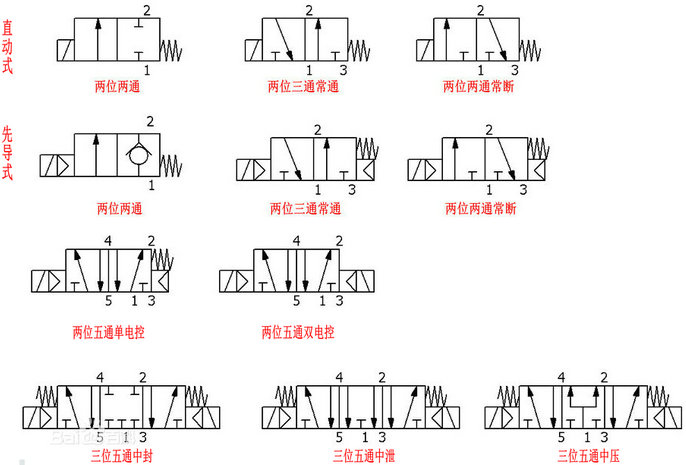
In front of the "several digits", you have to look at this valve to have several working states, it can be said that it is a few, if there is a pneumatic component symbol, it is better understood, on the icon represents the square of the valve body (with arrows inside) Or a few T lines) are just a few. The latter "several pass" means that there are several points on one of the squares (the point where the arrow line and the T line intersect), which is a few passes.
Three-position five-way solenoid valves come in three forms:
Middle seal: In the case where neither coil is energized, the pressure in the front chamber and the rear chamber of the cylinder remains unchanged after the last coil is de-energized, and the intake port is closed.
Medium unloading: In the case where neither coil is energized, there is no pressure in the front and rear chambers of the cylinder, the intake port is closed, and the pressure distribution in the front and rear chambers of the cylinder is discharged through the two exhaust ports of the solenoid valve.
Medium pressure: In the case that neither coil is energized, the pressure in the front chamber and the rear chamber of the cylinder remains unchanged after the last coil is de-energized, and the pressure is continuously applied to make the pressure in the front chamber and the back chamber of the cylinder The pressure at the intake end is the same, the air inlet is open, and the air outlet is closed.
Simply put, these three types have the same effect when the two coils are distributed. The difference is that the upper cylinder is connected and the two coils are not powered.
The middle seal is used for the pressure maintaining circuit, the medium pressure is used for the pressure regulating circuit, and the middle unloading is used for the unloading circuit.
The Intelligent Energy Storage System
The Intelligent Energy Storage System,Large Photovoltaic Grid-Connected Power,Grid-Connected Power Generation System,Photovoltaic Grid-Connected Power Generation System
Fuzhou Mei Li Cheng Imp&Exp Co., Ltd , https://www.mlc-solar.com