Abstract: A linear array LED dynamic display system using human eye vision persistence effect is developed. The system is driven by a motor to rotate a column of LEDs at high speed, and the LED is precisely controlled by the single-chip microcomputer to realize the display of characters, graphics and simple dynamic pictures. Using Visual Basic 6.0 to write the modulo software, the content to be displayed is converted into a digital signal, and the signal is transmitted to the display screen wirelessly or by wire. The system consists of PC software, mobile controller and display. It can change the display content and display mode in real time, which can be 360. Provide a clear display within the range.
Keywords: visual persistence; LED Display; data transmission
As a new type of display material, LED dot matrix has developed rapidly in recent years and has a good market prospect. Among them, LED large screen display is widely used in industry, transportation, commercial advertising, press release, sports competition, electronic scene simulation and other fields. However, the existing LED large screen requires a large number of LEDs and driving chips, and the control is complicated, making the display screen expensive and difficult to operate. At present, there are some research results in China that show the disadvantages of uneven brightness and real-time display. It is understood that the content to be displayed is generally burned into the chip, the content is fixedly displayed, and the display content and display mode cannot be changed in real time, which is inconvenient to use and expensive. This paper will apply a principle of visual persistence to develop a new type of ring display system. The motor drives a column of 64-bit LEDs to rotate at a high speed, and the precise control of the single-chip microcomputer realizes the clear display of characters, graphics and simple dynamic pictures, and can change the display content and display mode in real time. The system principle is ingenious, high in technical content, low in cost, and has broad market prospects, which can become a new economic growth point.
1 principle
1.1 Visual persistence effect
The visual persistence effect refers to the light emitted or reflected by the scene. The light image formed on the human retina will remain in the human vision for a period of time. Even if the scene disappears from the field of vision, the resulting light image will not disappear immediately. . The retention time is about 0.05 to 0.2 s. Experiments show that when the external light source suddenly disappears, the brightness of the human eye is gradually reduced exponentially. In this way, when a light source is repeatedly turned on and off, when the switching frequency is low, the human eye can find the change of brightness; and when the switching frequency is increased, the eye gradually cannot find the corresponding brightness change. The experimental results show that the critical flicker frequency is about 24 Hz. Therefore, a movie with 24 frames per second is seen as a continuous moving image. Because of the persistence of vision, when people repeatedly turn on and off the light at a critical flicker frequency, the subjective brightness perception is actually the average of the objective brightness. The visual persistence effect can be said to be the visual physiological basis of static image and moving image display. When the light source is pulsed (very small interval), people will feel that it is always shining, is the average brightness.
1.2 Display basic principles
This system uses the principle of visual persistence to achieve the display of characters or images. 64 super bright LEDs are arranged side by side in a row, and then the Chinese characters to be displayed are decomposed into 32×32 dot matrix, and the pattern is decomposed into 64×64 dot matrix. The data of each column is sequentially ordered by the single chip microcomputer. Sending to the LED dot matrix, the LED rotates by the high-speed rotation of the motor, and the content to be displayed is refreshed every turn, so that the effect of the display content seen by the human eye is the same as the continuous display of the plane due to the persistence effect of the human eye. .
2 hardware system
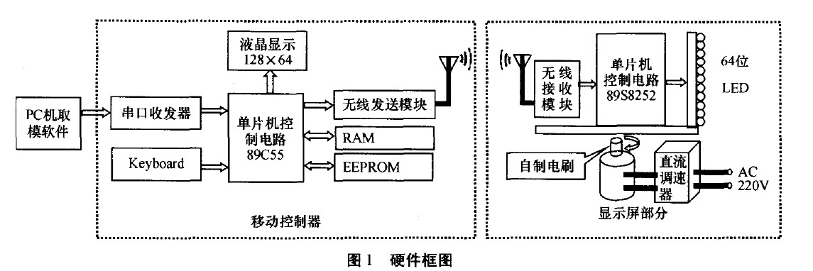
The hardware system mainly consists of two parts: the mobile controller and the display screen, as shown in Figure 1. The mobile controller is mainly responsible for receiving the data of the PC end software, adding the control characters and saving, and also sending specific control commands to the display screen, switching the display content, and changing the display effect. The display mainly has motor control speed and MCU control E 3j LED display content.
2.1 Mobile Controller
The mobile controller is composed of 5 parts: single chip AT89C55, serial port transceiver, wireless transmission module, keyboard, liquid crystal display.
The single-chip microcomputer selects AT89C55, the memory is large; the serial port transceiver is composed of the mature serial transceiver chip MAX232; the wireless transmission module uses the RFW102 chipset, which is a half-duplex DSSS wireless transceiver dual-use Ic, adopting ASK modulation mode, the operating frequency is 2.4 GHz, and the power consumption is very low. The chipset is short-range wireless transceiver Ic, the maximum transmission rate is 1 Mb/s; the keyboard control key is composed of 4 keys, which are “determineâ€, “exitâ€, “left shift†and “right shiftâ€, due to the number of keys. Less, so directly connected to 4 I / O ports; LCD display, 128 x 64 LCD module, can communicate directly with the CPU. The keyboard and LCD form a powerful remote control menu. Through the "exit", "OK", "left shift", "right shift" four keys to achieve data from the PC to receive data, save data, wirelessly send data and other powerful functions.
2.2 display
The display screen is mainly composed of a single-chip microcomputer control circuit, a column of 64-bit ultra-high brightness LEDs, a matrix of dots and a motor.
The MCU control circuit is mainly composed of 89S8252 MCU, wireless receiving module and several 74143373 latches. Using the cost-effective AT89S8252 microcontroller as the main controller, it comes with EEPROM, can be used as a display buffer, eliminating the need for conventional extended external memory, simplifying peripheral circuits, compatible with MCS51 instructions, is a powerful microcontroller. The circuit is designed to receive both wired and wireless data. After receiving the data in wireless mode, the data is stored in the EEPROM, so that data will not be lost after power off. In addition, eight 744353 are extended on the bus of the single-chip microcomputer, and each 7415373 controls 8 LEDs, so the single-chip microcomputer can flexibly control the off-state of 64 LEDs.
4. The motor part is composed of adjustable speed DC motor, DC governor and brush. The motor uses a speed-adjustable DC motor produced by Panasonic. Its rated working voltage is 220V, and the adjustable speed range is 0~6 000 r/min. The speed control system adopts the terminal voltage speed regulation method.
3 software system
3.1 PC software
PC software is programmed with Visual Basic 6.0. Can directly take the font, send data, friendly interface, easy to operate. The main function is to convert Chinese characters, English, numbers and graphics on a PC into real-time data information in real time, and transfer this data to the MCU through the serial port of the PC.
3.1.1 Design ideas
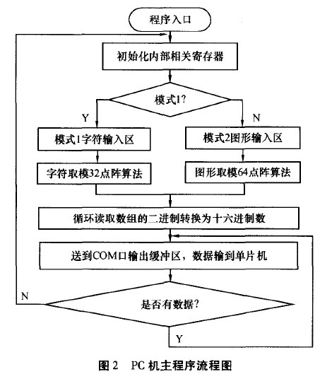
The software adopts real-time mode modulo: data graphics - data. By introducing the intermediate amount of graphics, the extracted fonts become flexible, and any font or symbol can be converted instantly. Pc machine software main program flow chart shown in Figure 2.
3.1.2 Character modulo flow
The content of the text box is set to empty when the user clicks on the text box. After the input is completed, the user presses the modulo button, and the program first determines whether the population is a character or a graphic. If it is determined to be in character mode, the extracted single character is mapped to the picture frame. Judging whether the current character is a Chinese character or a non-Chinese character, the Chinese character is a 32 x 32 dot matrix, and the English, numeric, and symbol are 16 x 32 dot matrix. The modulo part adopts the intersection point modulo. After the character is mapped to the picture frame, the intersection color is judged, the black is judged as 0, and the white is judged as 1. And output the modulo data to the output text box. The character extension function is designed for the accuracy of 32×32 dot matrix. When some characters are not displayed, the color selection is not only 32×32 intersection points, but also each intersection point and a small centered on the intersection point. The point in the range is color-coded. Once a point color in the range is judged to be black, the Boolean value at the intersection is set to 0. Blackface is the default font.
3.1.3 Graphic Molding Process
When the graphic mode is selected, the character modulo function is set to lock, leaving only the character function main button to be activated. Only the graphic frame appears on the interface, and the user can draw or load the image. After the input is completed, the user presses the modulo button, and the program first determines whether the entry is a font or a graphic. Automatically jump into the graphic font segment code when it is determined to be in graphics mode. The modulo part adopts the intersection point modulo. After the graphic is mapped to the picture frame, the intersection color is judged, the black is judged as 0, and the white is judged as 1. And output the modulo data to the output text box.
3.2 Mobile Controller Program
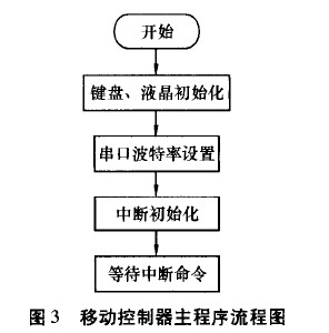
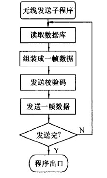
After the program is powered on, it is in a wait state. When the serial port interrupt comes to I, priority is given to the serial port interrupt. Sending wireless data is controlled through the keyboard and menu. The main program flow chart of the mobile controller is shown in Figure 3; the wireless transmission subroutine is shown in Figure 4.

3.3 Display program
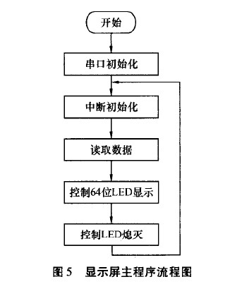
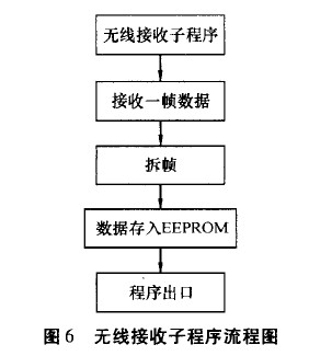
The LED is controlled by the MCU and the wireless data is received. After the data is received by the wireless module, the serial interface of the single chip receives the data and transmits it to the main control chip AT89S8252 for processing. When wireless data is transmitted, the received data is processed preferentially. The main program flow chart of the display is shown in Figure 5. The wireless data receiving subroutine flow chart is shown in Figure 6. Whether the display can clearly display the content is mainly considered from the following aspects: 1) The brightness of the LED controlled by the MCU: T=S/V, S is the width of the LED surface, which is the rotational speed of the motor; 2) The axis remains when the motor rotates Balance; 3) ambient light contrast.
4 Conclusion
The system displays English characters in 16×32 dot matrix mode, Chinese characters in 32×32 dot matrix mode, and graphics in 64×64 dot matrix mode. People can see clear dynamic display content within 360 degrees. The modulo software written in Visual Basic 6.0 can take the model in time and send data through the COM port. It can input content in real time, realize the touch of character graphics; can input graphic by hand, can display any graphic, and can display simple dynamic picture. The system adopts Bluetooth-like wireless technology, and the data transmission is stable, accurate, safe and reliable. Both wireless and wired data transmission methods ensure accurate data transmission. The LED surface width is 3 mm, the axial to column dot matrix LED distance is 160 mm, and the full screen can display about 22 Chinese characters. The display content size is mainly determined by the above conditions and rotation speed. The system has the characteristics of simple structure, unique perspective, novel design and convenient use. It has high social application value and can be widely used in commercial advertisements, conference notices, slogans, environmental decoration and visual persistence demonstration experiments in higher physics teaching. etc.
references:
[1]. AT89C55 datasheet http://
[2]. MAX232 datasheet http://
[3]. 89S8252 datasheet http://
[4]. AT89S8252 datasheet http://
[5]. COM datasheet http://
Spice up your imaging landscape via seamless convex or concave curved video walls with angles, curves and just about any other creative design;A wide range of pitch options allows for high resolution video playback as well as creative architectural displays;Our fanless design allows for a no-noise LED display solution that can fit in spaces of any size;Thanks to the light-weight design,up to 20 sq mts of soft LEDs can be packed inside one fligt case.So you get to save on both shipping and labor costs Indoor flexible LED displays are made of soft PCB and rubber material. It is extremely soft, can be made in any sizes and shapes for creative installations. it has a compact body design, 5mm thickness and magnetic connections . It can be fixed easily everywhere, including shopping malls, hotels, clubs halls, ect. Application Club and KTV entertainment arena.the television studio, personalized stage design, Club and KTV entertainment arena

Indoor Soft Led Display,Indoor Full Color Soft Led Display,Flexible Soft Led Display,Indoor Round Soft Led Display
Shenzhen Bako Vision Technology Co., Ltd. , http://www.rentalleddisplays.com