1. 400MHz-500MHz frequency band two or three power dividers, used in conventional radio communication, railway communication and 450MHz wireless local loop system.
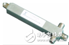
2, 800MHz-2500MHz frequency segment two, three, four microstrip series power divider, used in GSM / CDMA / PHS / WLAN indoor coverage project.
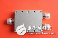
3, 800MHz-2500MHz frequency segment two, three, four cavity series power divider, used in GSM / CDMA / PHS / WLAN indoor coverage project.
4, 1700MHz-2500MHz frequency section two, three, four cavity series of power dividers, used in PHS / WLAN indoor coverage project.
5. Microstrip two- and three-power splitters used in small-volume devices in the 800MHz-1200MHz/1600MHz-2000MHz frequency range.
There are three types of existing couplers, and the system used is the same as the system of the above splitter, and will not be repeated here.
Second, the coupler seriesThe coupling degree is divided into: 5 dB, 7 dB, 10 dB, 15 dB, 20 dB, 25 dB.
1. Microstrip series coupler 800MHz-2500MHz frequency band
2. Cavity series coupler 800MHz-2500MHz frequency band
3, cavity series coupler 1700MHz-2500MHz frequency segment
Third, the difference between power divider and couplerPower splitter, coupler, as its name suggests, power splitter, power coupler;
Power splitters and couplers are basically used in passive components in radio frequency signals to distribute signals according to actual needs.
A combiner is a passive device that combines signals of different frequency bands into one signal output. The power loss is different, and the process has a relatively large relationship.
The power splitter and the coupler are power distribution devices, but the power splitter is evenly divided. For example, the two power splits are equally divided into two paths, and the three power splits are equally divided into three paths; the coupler coupled output and the through-end distributed power Uneven, of course, both the power splitter and the coupler are lossy.
Passive devices are classified into microstrip type and cavity type according to the implementation principle. The microstrip type utilizes a 1/4 wavelength microstrip line, and the cavity type utilizes a resonant cavity.
In contrast, microstrip devices are inexpensive but have an insertion loss of 0.5 dB, while the cavity type is more expensive but the insertion loss is only 0.1 dB.
Power splitter is the most common passive device used to divide a signal into multiple signals, which plays the role of equal power distribution. Commonly, there are two power points, three power points, and four power points. The reverse application of the power splitter becomes a combiner.
The coupler divides one signal into two signals that are not equal. The coupler has three terminals, the input, the through and the coupling. According to the power difference between the input and the coupling end, it can be divided into 5dB, 6dB, 7dB, 10dB, 15dB and other models. It can also be divided into 1:1, 2:1, 4:1 and other models according to the ratio of the through and the coupling ends. .
The 3dB bridge is a special coupler with two inputs. The ratio of the through and the coupling ends is 1:1, so the power difference between the input and the coupling is 3dB. The 3dB bridge is used to combine the signals of the base station, which is equivalent to the combined + two power points in effect.
The combiner is used for signal combining of different systems, such as GSM/PHS/WLAN/WCDMA, so it can be understood as
Frequency combination. A filter is required in the combiner.
The power splitter can also be used as a combiner, such as a two-power split. However, it is noted that the two-power split, 3dB bridge and combiner are also different in the process of use, such as the consideration of insertion loss, power, price, isolation and other conditions.
1, two power points and 3dB bridge:
The two power points are similar to the 3dB insertion loss and isolation. The two-power splitter uses 3.8dB of insertion loss, 25dB of isolation, large standing wave, two ports in, one port out. The 3DB bridge insertion loss is 3.2, the isolation is also 25, and the standing wave is general. But there are two output ports, for example, two 30 outputs are two 27. The output of the 3dB bridge can also be set at will, two in and one out, one in and two out, two in and two out, in fact, one more It is enough to connect a load with sufficient power. The fact that the load is not connected is actually disconnected from the factory, and has no effect similar to the load. However, only 3dB can be used when the standing wave ratio is high. In addition, consider the power consumption of the device. Then what I can't figure out is: When the project chooses to use, is there no substantive difference between the two?
2. Two-power split, 3dB bridge and combiner:
Combiner: It is a frequency selective combiner that works in filter multiplex mode. It can realize more than two channels of signal synthesis, and can achieve high isolation and synthesis. It is mainly used for combining different frequency bands and can provide the minimum interference between different systems. The insertion loss is the smallest, the out-of-band rejection is the best, the band isolation is the largest, and the input and output of the different system equipment must be used.
3dB bridge: It is the same frequency combination road, which can only realize the synthesis of two signals. The isolation is low, and the two-way equal-amplitude output can be realized. It is also the most expensive.
Power splitter: It is a common frequency combining circuit, which can realize multi-channel synthesis, and the isolation is low, and only one output can be provided.
Ningbo Xingchuangzhi Electric Appliance Co.,Ltd. , https://www.xingchuangzhi.com