Abstract: This paper describes the hardware and software design of an industrial air conditioner intelligent controller based on Internet. The controller can not only complete the routine control function of the electrical appliance, but also communicate with the embedded network interface module, receive the command sent by the upper computer, process and return the corresponding parameters, and realize the remote monitoring of the device by the user. The actual operation results show that the scheme is practical and feasible. The controller has the characteristics of low cost, simple and rapid development, and flexibility.
1 Introduction
The monitoring of equipment based on the network has become a major application field at present, such as remote operation of industrial air conditioners through the Internet, including power on, power off, temperature adjustment, and the like. In addition to completing the regular functions, it also needs to communicate with the external network, receive the commands sent by the remote users over the Internet, analyze the instructions and perform the corresponding operations, and return the working status parameters of the devices as needed. In this paper, the software and hardware design of the industrial air conditioner intelligent controller is introduced in detail. The controller communicates with the embedded network interface module through the serial port, so that the electrical appliance can access the Internet and complete communication with the external network.
2 How does industrial air conditioner work?
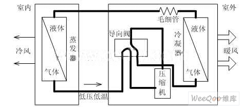
Figure 1 Schematic diagram of industrial air conditioning refrigeration
The principle of industrial air conditioning refrigeration is shown in Figure 1. When industrial air conditioner is working, the low-pressure and low-temperature refrigerant vapor in the refrigeration system is sucked by the compressor, compressed into high-pressure, high-temperature superheated steam and discharged to the condenser; The outdoor air flows through the condenser, taking away the heat released by the refrigerant, and condensing the high-pressure, high-temperature refrigerant vapor into a high-pressure liquid. The high-pressure liquid flows through the throttling capillary to reduce the temperature and flows into the evaporator, and evaporates at the corresponding low pressure to absorb the surrounding heat; at the same time, the indoor side fan allows the indoor air to continuously enter the ribs of the evaporator for heat exchange, and the exothermic The cooled gas is sent to the room. In this way, the indoor and outdoor air continuously circulates to achieve the purpose of lowering the temperature.
3 controller hardware detailed design
The hardware block diagram of the industrial air conditioner intelligent controller is shown in Figure 2. It can be seen from the figure that the hardware of the industrial air conditioner intelligent controller is based on the AT89S52 microprocessor, mainly consisting of power circuit, panel button, infrared receiving circuit, temperature detecting circuit, serial communication interface, digital display circuit and relay driving circuit. Part of the composition.
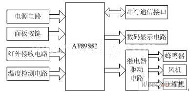
Figure 2 Block diagram of industrial air conditioning intelligent controller
3. 1 power circuit
There are three voltages on the main control board: AC220V, DC12V and DC5V. AC220V directly supplies power to compressors and fans; DC12V and DC5V are used for power supply of relays and micro control systems. The power supply circuit is shown in Figure 3. The power transformer converts the voltage of the AC grid 220V into the required voltage value, and then inputs it from the socket J1, and performs full-wave rectification through the rectifier bridge. It is composed of a parallel 2200u/35V electrolytic capacitor and a 0.1μF capacitor. The filter circuit filters out the ripple to get DC12V, and then the voltage is regulated at +5V through the three-terminal regulator tube 7805.

Figure 3 power circuit
3. 2 temperature detection circuit
The digital temperature sensor DS18B20 is selected for design. The temperature measurement range is -55°C-+125°C. It can be programmed to 9-bit-12-bit A/D conversion accuracy. The temperature resolution can reach 0.0625°C. The measured temperature is extended by symbols. 16-bit digital serial output; its working power can be generated either at the far end or by parasitic power supply; its convenience lies in the single-wire interface design, so that the processor only needs to connect one data line to It performs all operations to achieve the transfer of operational commands and measurement data, saving a large number of leads and logic circuits. The above features make the DS18B'20 widely used in temperature measurement and control systems.
The DS18B20 and the microcontroller are typically connected in two ways: (1) Parasitic power mode with both VDD and GND terminals grounded. (2) External power supply mode, VDD terminal is powered by 3V~5.5V power supply. This design uses an external power supply.
3. 3 digital display circuit
The display module is mainly composed of a digital LED display block and a 74HC164. The 74HC164 is a unidirectional 8-bit shift register that can realize serial input and parallel output. The 74HC164 is easy to program and cost-effective. The two I/O ports of the single-chip microcomputer are used to complete the serial display connection with the display module, wherein the P2.4 port of the single-chip microcomputer is used as the shift pulse output end, and the P2.5 port is used as the data output end. The P2.2 port of the MCU is connected to the CLK terminal of the 74HC164, and the high and low level of the P2.2 port output of the MCU is the clock pulse for shifting the data of the 74HC164. At the instant when the 74HC164 obtains the clock pulse, if the data input terminal is high level , then there will be a 1 into the 74HC164 internal, if the data input is low, then there will be a 0 into its internal, so 8 cycles can transfer an 8-bit data to the 74HC164. The output of the 74HC164 (parallel output) is directly used as the segment selection control signal of the digital tube. The P2.0 port and P2.1 port drive output of the MCU display the bit selection control signal. The segment code driving circuit is shown in Figure 4.

Figure 4 shows the drive circuit
3. 4 Ethernet control and serial communication module design
The Ethernet control module acts as a bridge between the Ethernet/Internet and the microprocessor. The data from the microprocessor is packaged onto the Ethernet, or the data on the Ethernet is received for processing by the host processor. The core is the Ethernet control chip RTL8019AS. In order to make the RTL8019AS work with the 8-bit microprocessor, it is necessary to set the hardware, mode and related parameters.
The Ethernet control chip RTL8019AS implements Ethernet media access layer (MAC) and physical layer (PHY) functions, including MAC data frame assembly/split and transmit and receive, address recognition, CRC encoding/checking Manchester codec, and receiving noise. Suppression, output pulse shaping, timeout retransmission, link integrity testing, signal polarity detection and correction.
The serial communication module is a bridge between the device controller and the embedded network interface module. Since the serial data interface of the microcontroller is not the standard RS-232-C serial port, MAXIM's MAX232 level conversion chip is used to connect the serial data interface of the microcontroller to the standard RS-232-C serial interface. The MAX232 is a dedicated chip that converts both RS232 and TTL logic levels. The chip contains two receivers and drivers and a supply voltage converter, and requires only a single +5V supply. The hardware interface of the MAX232 chip is very simple. The serial receiving and transmitting end of the MCU can be directly connected to the corresponding port of the MAX232. The external 1.0μF electrolytic capacitor can make the MAX232 output RS-232-C serial communication. The required ±10V signal level. Since the MAX232 chip does not have a chip select terminal, it only functions as a level shift in the application system, so it does not occupy the external data storage space of the microcontroller.
3. 5 relay drive circuit
In the single-chip application system, the switch output circuit mainly completes the output of the action signal and is used to control the switching state of the compressor and the fan. Since the output signal is not enough to drive the switching action of the relay, ULN2003A is used to amplify and drive the signal between the signal output port of the MCU and the relay. ULN2003A is composed of 7 sets of Darlington transistor arrays and corresponding resistor networks and box diodes. It has the ability to drive 7 groups of loads at the same time. It is a single-chip bipolar high-power high-speed integrated circuit; it has high current gain and It has the characteristics of strong load capacity, wide temperature range and high working voltage, and is suitable for driving high-power devices such as relays and displays.
The relay drive circuit design is shown in Figure 5. The MCU control signal is output through the P1.0~P1.3 port, and the signal is latched in the 74LS273 through the control of P3.4. The output of 74:LS273 passes through the Darlington drive. The ULN2003A is reverse amplified and applied to the input of the relay to operate the compressor and fan as required. The 74LS273 latches the control signal to increase the output power on the one hand, and also prevents the control from malfunctioning when the microcontroller is reset.

Figure 5 relay drive circuit
4 software design and implementation
The system software is written in C51, which adopts the modular design idea and consists of three parts: main program module, each function subroutine module and interrupt service subroutine module. The functions of the main program are system initialization, control program direction and call function subroutine; function subroutines include subroutine such as data acquisition, digital display, fan and compressor control; interrupt service subroutine includes remote control reception, timed interrupt processing and so on. The main program modules are described below.
The main program is the hub of the entire control system software. The main program organically calls various subroutines and modules in the system, so that they form a close-knit whole and orderly complete the various operational instructions. After the system is powered on or reset, the system first initializes, including the initialization of each register and chip; then samples and weights the room temperature; the initial serial communication module determines whether to receive the command and data sent by the gateway, if received Command and data, set the corresponding parameters and flag bits; call the keyboard scanner to check if there is a button press, if there is a button press, identify the button and set the corresponding parameters and flag bits; call the display module to display the set temperature Information such as current room temperature, timing time, wind speed, function and timing status; calling the function query and processing module enables the system to work according to the set parameters and flag bits. As long as the system is powered on, the main program cannot be stopped and remains in the loop waiting state, so the main program does not end the running command.
The author of this article is innovative:
This paper realizes the software and hardware design of industrial air conditioner intelligent controller. The air conditioner controller can not only complete the normal functions, but also communicate with the embedded network interface module according to the communication protocol through the communication interface, thereby realizing remote monitoring of the device by the user.
references:
[1]. AT89S52 datasheet http://
[2]. DS18B20 datasheet http://
[3]. 74HC164 datasheet http://
[4]. RTL8019AS datasheet http://
[5]. MAXIM datasheet http://
[6]. MAX232 datasheet http://
[7]. RS232 datasheet http://
[8]. TTL datasheet http://
[9]. ULN2003A datasheet http://
[10]. 74LS273 datasheet http://
:
The Description Of Flat Amplified TV Antenna
Innovative flat,razor-thin antenna design.
Flat Amplified Tv Antenna It has high gain and low error rate Digital TV signal reception,and a significant signal enhancement in actual ues.Increase the reception of TV programs,and eliminate the pause the mosaic images.
Multi-directional design pulls in signals from all directions.
Fast and easy to set up - Unwrap,Plug it in and Scan channels.
IMPORTANT TIP BEFORE YOU BUY:You have to make sure your TV is Digital TV, the local signal is COVERED.You can put it on the wall,on the table or on the window(strongly recommended) and it will make you enjoy watching crystal clear digital & HD shows with many opportunities.
The Specification Of Flat Amplified TV Antenna
Features
1.Support 1080p.
2.50 miles range.
3.Multi-directional capability.
4.call out all "Free" channels.
5.Connector Type:F Male.
6.V.S.W.R.:<1.5
7.Working Frequency: 174~240MHz,470~862MHz.
8.Gain:25 dBi(with amplifier).
Picture show


Flat Amplified Tv Antenna
Flat Amplified TV Antenna,TV Antenna With Amplifier,Digital Flat TV Antenna,Flat TV Antenna
Shenzhen Yetnorson Technology Co., Ltd. , http://www.yetnorson.com