As one of the greatest inventions of mankind in the 20th century, robots have undergone rapid changes in just 40 years. With the development of computer technology, communication technology, sensor technology, etc., the interaction between robots has become a hot spot in robot technology .
This paper designs a robot chasing control system based on Motorola MC68HC08 series MCU, which is used to study the simple interaction between robots.
Mobile robot behavior description
In this system, we named one of the two mobile robots "cat" and one named "rat". When neither of the two robots can receive the signal from the Other party, the robot "cat" advances in an S shape, and the robot "rat" swings 180 degrees in place; when the robot "cat" detects a signal from the robot "rat", The straight line chases the direction of the robot "rat", while the robot "rat" receives the signal of "cat" and moves forward in a straight line to avoid the chase of the "cat" until it escapes the receiving range of the "cat" and repeats The behavior when the signal is not received; if the "cat" cannot find the existence of the "rat" for a period of time, an audible alarm is issued. Throughout the process, due to the unknown environment, both "cat" and "rat" have obstacle avoidance control, and can play different music according to different behavioral states.
System hardware design
The circuit designs of the two cats, "cat" and "mouse" are basically the same, which are composed of a single-chip microcomputer system, an infrared transceiver module, a motor control module and a voice module. The difference is that the arrangement of the infrared transmitting tube and the receiving tube array is different. The MCU uses Motorola's 8-bit microprocessor M68HC908GP32 (42-pin package); the infrared transceiver module uses a simple infrared transceiver circuit composed of PT2262 and amplifier; the motor control module uses L293D for motor drive; the voice module uses ISD25120 to control playback. In addition, the system power module uses a 12V dry battery.
Single chip system
MC68HC08 family of microcontrollers is Motorola Inc. in 1999 introduced 8-bit microcontroller with fast, powerful, low power consumption and price and so on.
The MC68HC908GP32 microcontroller we selected in the design is the first batch of MC68HC08 series microcontrollers. It is characterized by abundant on-chip resources, high performance, low price, and various protection functions. It is suitable for building various data processing platforms. . Here we mainly use it to complete infrared information fusion, motor control and voice playback control.
In the design, the main ports of the two MCUs are set to the same, as shown in Table 1. In addition, the three contact switches that are avoided are controlled by PTB0, PTB6, and PTA7.
Infrared transceiver module
The infrared transmitting module uses an infrared transmitting circuit composed of an array of PT2262 and an infrared transmitting tube. The infrared receiving circuit is composed of an infrared receiving tube array and an amplifier. The received signal is input to the PTB7 port of the MCU, and after A/D conversion, it is sent to the processor to control the behavior conversion of the robot.
Motor control module
The motor drive circuit uses an integrated circuit L293D based on a bipolar H-bridge type pulse width adjustment PWM. L293D has many advantages, such as continuous current; the motor can run at four corners; the motor has a micro-vibration current when it stops, which plays the role of “power lubricationâ€, eliminating the dead zone of static friction in forward and reverse directions; The L293D generates an enable signal through internal logic. The input of the H-bridge circuit can be used to set the direction of motor rotation, and the enable signal can be used for pulse width adjustment (PWM). In addition, the L293D integrates two H-bridge circuits onto one chip, which means that two motors can be controlled simultaneously with one chip.
The robot has three wheels, two with motor control and the other with a universal wheel, so use one L293D for control. Connect the two PMW control signals to the enable pins EN12 and EN34 of the two motor controls respectively. Adjust the PWM duty cycle to adjust the motor speed. Connect the motor forward and reverse control lines to IN1, IN2, IN3, and IN4, respectively, and control the forward and reverse rotation of the two motors by writing different values.
Voice module
In order to distinguish the different states of the mobile robot, we can make different sounds while playing different actions. In order to achieve this, the voice control part uses the voice chip ISD25120. The recording and playback time of the ISD25120 is 120 seconds, and the recording can be divided into up to 600 segments. As long as the address A0"A9 is assigned before the segment recording/playback operation (not less than 300 nanoseconds), the recording and playback functions start from the set start address.
At the time of design, in addition to using the microcontroller to control the reset and trigger terminals of the ISD25120, the playback start address of the four-bit I/O control chip is used. During initialization, the different information of the two robots are respectively written into the A0"A3 of the voice chip, and the playback is selected; during the action, when the behavior changes, new information is written, the playback selection is changed, and different music is played. .
System software design
The system software is mainly composed of a main program module, an interrupt service program module, a voice control module, and a motion planning module. The software portion of the entire system is written in assembly language.
in conclusion
Experiments have shown that the two robots can correctly complete the chasing action without being disturbed by the outside world. This design provides a test platform for studying simple interactions between robots. In future research, by changing the sensor position and internal procedures, you can change the interaction between the two, such as collaboration, for further research.
The positive active material is mainly made of nickel, and the negative active material is mainly an alkaline battery made of hydrogen storage alloy.Nickel-metal hydride (nimh) batteries are modified from nickel-cadmium (nicd) batteries, which offer higher capacitance, less obvious memory effects, and lower environmental pollution at the same price.The special charger can be used for quick charging in one hour. The self-discharge characteristic is better than nickel-cadmium battery, which can be retained for a longer time after charging and can be repeated for more than 500 times.
The charger adopts high frequency switching rectifier power-supply module. The working process of the charger is controlled by microprocessor in real-time, automatic power on/off, simple operation, safe and reliable. The user can view the operation parameters and working status through the touch screen.
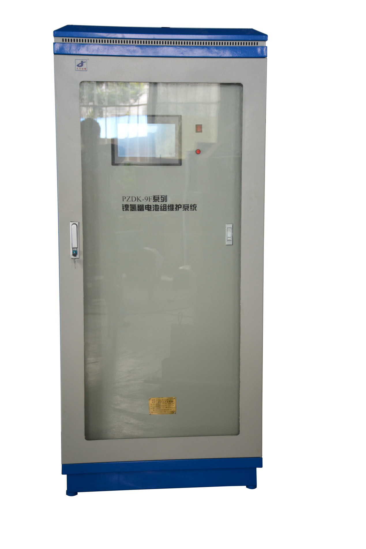
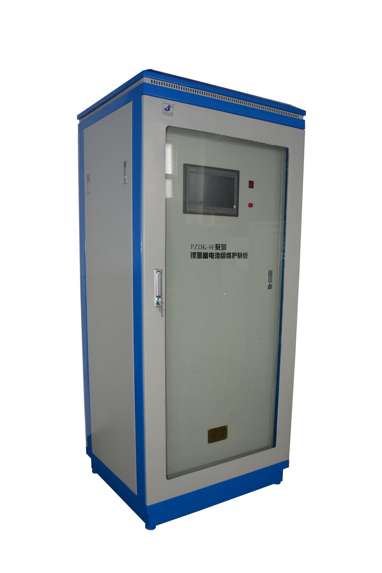
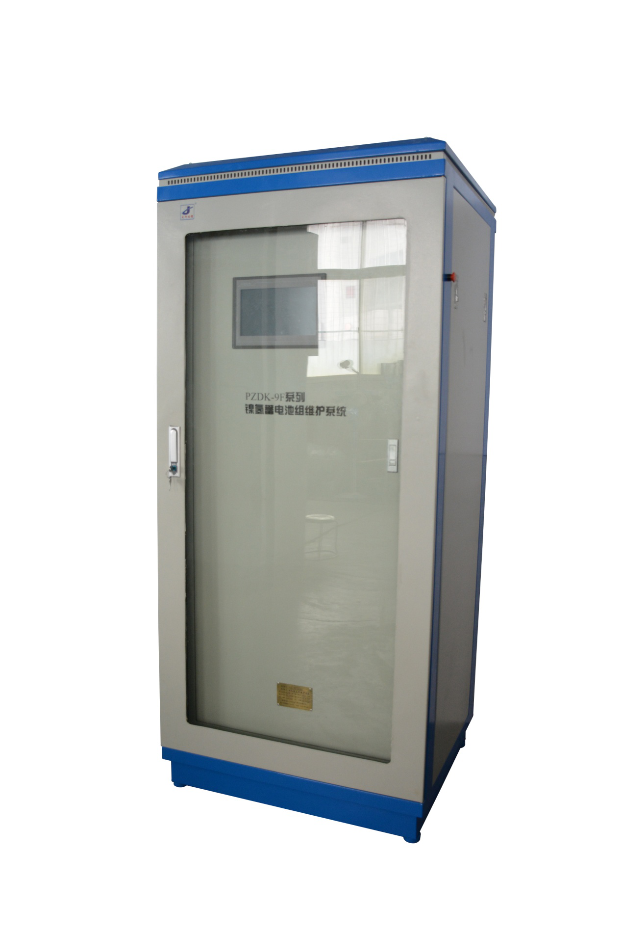
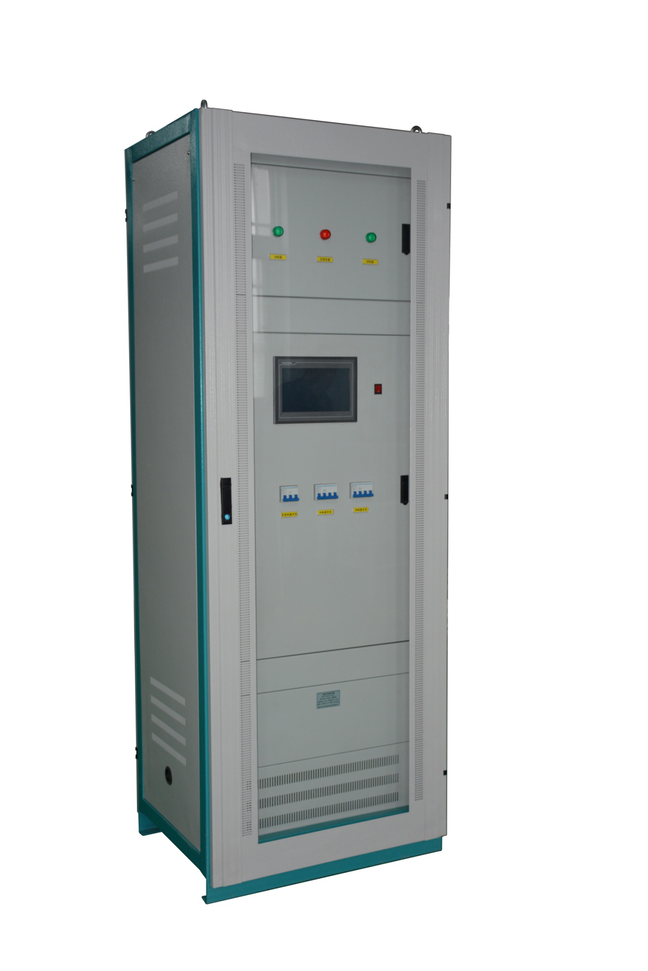
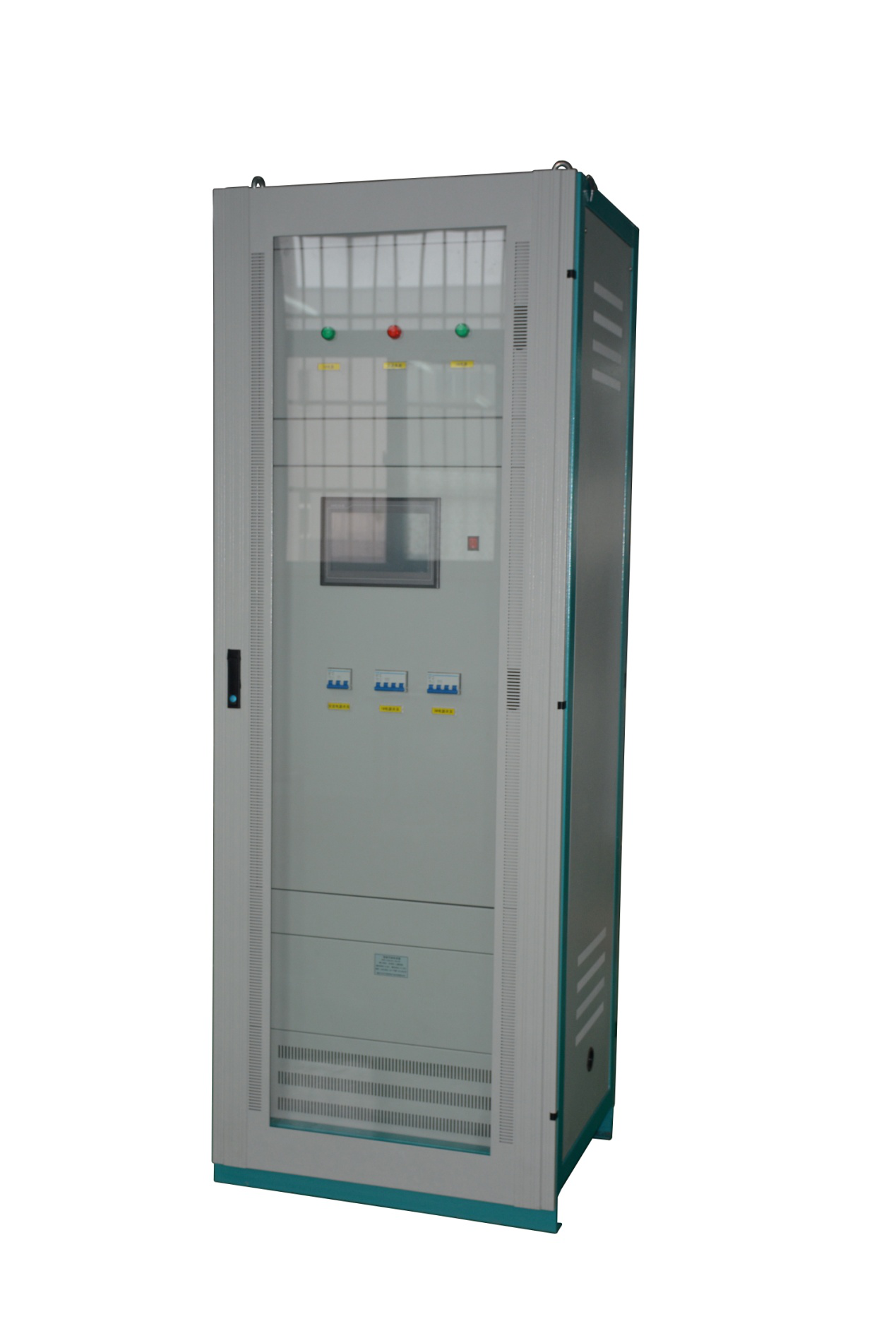
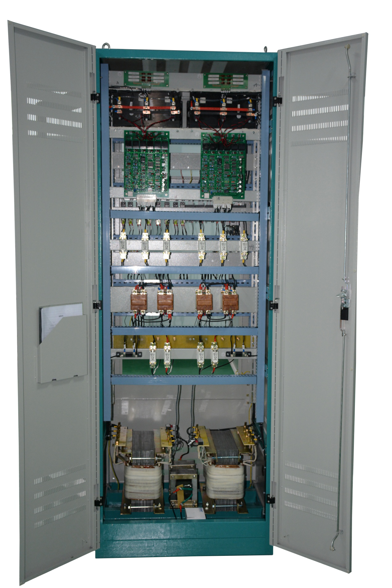
Nimh Battery Charger,Industrial Battery Charger,Substation Battery Charger,Nimh Battery Pack Charger
Xinxiang Taihang Jiaxin Electric Tech Co., Ltd , https://www.agvchargers.com