1. Introduction
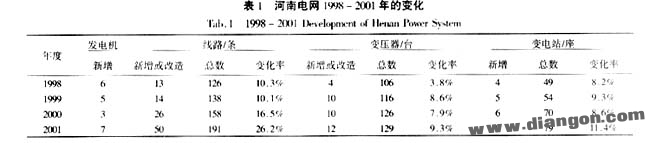
In recent years, the development of Henan Power Grid has been rapid and significant. Table 1 outlines the major changes in the grid since 1998. As the power grid expands, the workload for relay protection setting calculations has increased considerably. With ongoing reforms in the power system, the number of personnel in the Protection Section has decreased from 10 in 1996 to just 8 today, making each individual's responsibilities more demanding. This situation has led to a critical need for simplifying the tuning process while ensuring compliance with regulations.
Currently, relay protection setting calculations for systems above 220 kV in China follow the "Regulations for the Operation of 220-500 kV Grid Relay Protection Devices," issued by the Ministry of Electric Power in 1994. Before that, domestic protection was mainly based on rectifier and transistor types, with some integrated circuits and microcomputer protection beginning to emerge. Implementing impedance relays for these older technologies was complex, leading most manufacturers to only provide phase-to-phase distance protection without grounding distance protection. However, with the rise of microcomputer protection, grounding distance protection has become widely used in Henan, increasing the workload for setting calculations.
Grounding distance protection shares similarities with zero-sequence protection in function, and their setting calculations are comparable. Based on these characteristics, several simplifications can be made to the setting process. We simplified the work by eliminating the zero-sequence I segment, streamlining the calculation of the zero-sequence IV segment, and unifying the phase-to-phase and grounding distance protection settings.
2. Elimination of the Zero Sequence I Segment
2.1 Impact of Line Parameters on Zero Sequence and Ground Distance Protection
When ground distance protection was not widely implemented, zero sequence protection played an essential role in detecting ground faults. However, inaccuracies in zero sequence parameters introduce uncertainty into the calculation process. Since the zero sequence I segment operates without delay, these errors can lead to misoperations. While measured parameters are preferred, they are often unavailable due to various constraints, especially for older lines. The error in calculated zero sequence parameters is typically larger than that of positive sequence parameters.
Moreover, the segmented insulation design in 500 kV lines affects zero sequence parameters differently depending on whether the ground insulation gap is broken down or not. These factors complicate the accuracy of zero sequence calculations. The current short-circuit programs also tend to simplify the handling of zero-sequence mutual inductance, further contributing to errors.
2.2 Protection Range of Zero Sequence I Segment vs. Grounding Distance I Segment
The protection range of the zero sequence I segment is variable, depending on the system mode. In some cases, it may only cover less than 10% of the line, even failing to detect faults at the line’s end. In contrast, the grounding distance I segment reliably covers 70% of the line, with a stable range unaffected by system changes. Modern microcomputer protection systems use advanced features like quadrilateral characteristics and resistance compensation, giving grounding distance I segments better performance in handling transition resistances compared to zero sequence I segments.
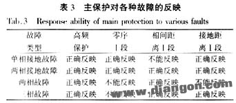
2.3 Main Protection for Various Faults
Common line protections include high-frequency protection, zero sequence I segment, phase I distance segment, and grounding distance I segment. Table 3 illustrates the different types of protection for various fault scenarios. Both zero sequence and grounding distance protection can correctly reflect the fault, but grounding distance offers more stability and reliability.
2.4 Action Time of Main Protection
Current 220 kV line protections in Henan, such as Type 11, 15, 901B, and 902B, have similar action times for both zero sequence I and grounding distance I segments. Grounding distance I segments offer a stable protection range, better resistance to transition effects, and are less affected by zero sequence parameter errors. Therefore, eliminating the zero sequence I segment does not impact the overall system performance.
Many experts support the elimination of the zero sequence I segment. For example, LFP series microcomputer protection originally did not include this feature. During early implementation, it was added based on operational requirements. However, in practice, removing it had no negative impact on the grid. It reduces the risk of misoperation due to zero sequence parameter errors and eases the pressure during infrastructure commissioning. Additionally, it allows for smoother operation mode adjustments and reduces hidden risks in grid management.
3. Simplified Calculation of Zero Sequence IV Segment
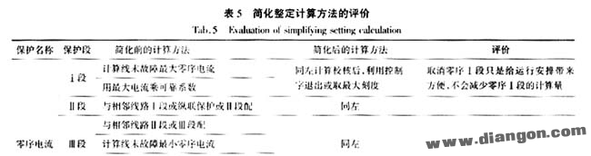
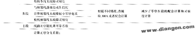
Before the implementation of the procedure, the zero sequence IV segment was coordinated with adjacent III or IV segments, requiring sensitivity at the end of the adjacent line of at least 1.2. According to the literature [1], the zero sequence IV segment must meet specific conditions, such as setting to 300 A for 220 kV lines, 150 Ω for 330 kV lines, and 300 Ω for 500 kV lines. If the zero sequence III segment exceeds 300 A, the IV segment is set directly to 300 A, matching with the adjacent III segment. This approach significantly reduces calculation time.
4. Unified Calculation of Grounding Distance and Phase-to-Phase Distance
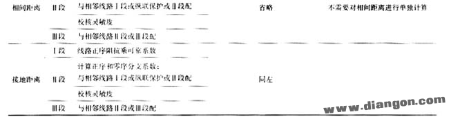
Under similar conditions, grounding distance settings should be less than or equal to phase-to-phase distance settings. By analyzing the requirements of both, we explored the feasibility of unifying their calculation methods. Grounding distance I and phase-to-phase distance I share similar formulas, with grounding distance I having a higher reliability coefficient. This allows for more reliable protection against out-of-zone faults.
For grounding distance II and phase-to-phase distance II, the sensitivity requirements are identical. Grounding distance III is generally less sensitive than phase-to-phase distance III, but according to the regulations, it can be disabled if phased zero sequence protection is already in place. This reduces the workload and ensures compatibility between different protection systems.
5. Conclusions
The proposed simplification method for relay protection calculations fully meets the required standards. It improves efficiency and increases flexibility in operation mode planning. After applying the simplified method, the zero sequence calculation workload is reduced by 1/5, and the distance protection workload is reduced by 1/3. These improvements enhance the overall performance of the power grid.
Intelligent classroom interactive blackboard,Educational interactive blackboard,Electronic blackboard
Jiangsu Qilong Electronic Technology Co., Ltd. , https://www.qilongtouch.com