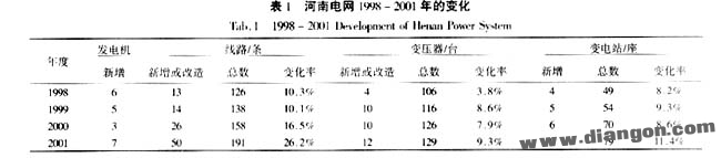
1 Introduction In recent years, the development of Henan Power Grid has been rapid. Table 1 shows the major changes in the grid since 1998. As the grid expands, the workload for relay protection setting calculations has increased significantly. With power system reforms, the number of personnel in the Protection Section decreased from 10 to 8, increasing individual workloads. This led to a need for simplification without violating regulations.
Currently, the relay protection settings for 220 kV and above systems in China follow the "Regulations for the Operation of 220-500 kV Grid Relay Protection Devices," issued by the Ministry of Electric Power in 1994. Before that, domestic protection was mainly based on rectifier and transistor types, with some integrated circuits and microcomputer protection beginning to be used. Impedance relays were complex to implement, so most products had only phase-to-phase distance protection and no grounding distance protection. Despite having calculation procedures for grounding distance, it was not widely applied. However, with the popularity of microcomputer protection, grounding distance protection has become common in Henan Power Grid, adding more work to the tuning process.
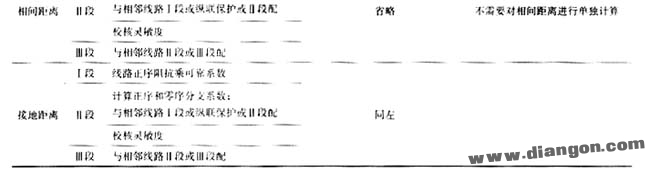
Grounding distance protection is similar to zero-sequence protection in some functions, and their setting calculations are comparable. Based on these characteristics, we simplified the process by canceling the zero-sequence I segment, simplifying the zero-sequence IV segment calculation, and unifying phase-to-phase and grounding distance protection settings.
2 Cancel the Zero Sequence I Segment 2.1 Influence of Line Parameters on Zero Sequence and Grounding Distance Protection When grounding distance protection was not widespread, zero sequence protection played an irreplaceable role. However, inaccurate zero sequence parameters can introduce uncertainties into the calculation, potentially leading to misoperations. Calculated zero sequence parameters often have larger errors than positive sequence parameters. For example, in Table 2, the error in zero sequence parameters is significantly higher than in positive sequence parameters.
The main reason for this large error is the inability to accurately reflect geological conditions in zero sequence parameter calculations. Additionally, as noted in [5], the segmented insulation design of 500 kV lines affects zero sequence parameters depending on whether the ground insulation gap is broken down or not.
Although measured line parameters are required during infrastructure projects, they are often unavailable due to various reasons. Old lines typically lack measured data, making testing difficult. For 500 kV lines, it is challenging to obtain accurate zero sequence parameters because the test current may not be sufficient to break the ground insulation gap.
Current short-circuit calculation programs simplify zero-sequence mutual inductance processing, which contributes to errors in zero-sequence current calculations. While the impact on zero-sequence II, III, and IV segments is relatively small due to their delayed operation, the zero-sequence I segment is instantaneous. If it malfunctions, it could lead to serious issues. Some provinces now increase the reliability factor, but there is no standard. A high reliability factor may cause the zero-sequence I segment to lose sensitivity in shorter lines, reducing its effectiveness.
Grounding distance protection uses IA + K·3I0, where K = (Z0 - Z1)/(3Z1). The error in zero sequence parameters has less impact on grounding distance protection.
2.2 Zero-Sequence I Segment and Grounding Distance I Segment Protection Range The protection range of the zero-sequence I segment is not fixed. It can vary significantly with system mode changes. In normal conditions, the range is often much less than 70%, even below 10%. In some cases, the zero-sequence I segment may not activate during a fault at the line's end.
Grounding distance I segment can protect up to 70% of the line, with a stable range unaffected by system changes. Microcomputer line protection often includes quadrilateral characteristics or certain R-direction compensation, improving anti-transition resistance performance compared to zero-sequence current protection.
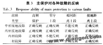
2.3 Main Protection for Various Faults Common line protections include high-frequency protection, zero-sequence I segment, phase I distance, and grounding distance I segment. Table 3 shows different protection types for various faults. Both zero-sequence and grounding distance protection can correctly reflect simple faults.
2.4 Main Protection Action Time Modern 220 kV line protection in Henan includes Type 11, 15, 901B, and 902B. Table 4 shows the operation times of various protections. Both zero-sequence I segment and grounding distance I segment have similar action times, and the latter offers a more stable protection range and better anti-transition resistance capability. Therefore, canceling the zero-sequence I segment does not affect the overall system performance.
Many domestic experts support the cancellation of the zero-sequence I segment. LFP series microcomputer protection originally did not consider it. Early on, it was added due to the lack of grounding distance protection. In practice, the cancellation had no negative impact. It reduces the risk of misoperation caused by zero-sequence parameter errors and eases pressure during project commissioning. It also allows step-by-step setting adjustments, reducing hidden dangers in grid operations.
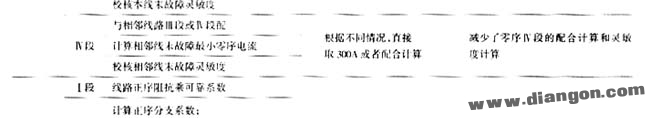
3 Simplified Calculation of the Zero-Sequence IV Segment Before implementing the procedure [1], the zero-sequence IV segment was coordinated with adjacent III or IV segments, requiring a minimum sensitivity of 1.2 at the end of the adjacent line. According to [1], the zero-sequence IV segment should be set to meet specific grounding resistance values. If the zero-sequence III segment exceeds 300 A, the IV segment is set directly to 300 A and matched with the III segment. Otherwise, it is matched with the III or IV segment of the adjacent line. This method saves significant time.
4 Unification of Grounding Distance and Phase-to-Phase Distance Calculation According to [4], under the same conditions, grounding distance settings must be less than or equal to phase-to-phase distance settings. This paper further discusses the feasibility of unifying the calculation of both. The grounding distance I and phase-to-phase distance I share the same formula, but the reliability coefficient for grounding distance is slightly higher. If the phase I distance is calculated using the grounding distance I coefficient, it can prevent overshoot more reliably.
When a single-line fault occurs, whether it's a line or transformer fault, the impact on users and the grid is similar. Thus, the I segment protection can penetrate the transformer. In such cases, the formulas for grounding distance I and phase-to-phase distance I are the same. Therefore, the calculation of both segments can be unified.
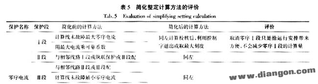
5 Conclusions Our proposed relay protection setting simplification method fully meets the requirements of the regulation. The simplification improves efficiency and increases operational flexibility. Table 5 provides an evaluation of the simplified method. After implementation, the zero-sequence calculation reduces coordination and sensitivity tasks by 1/5, while distance protection reduces cooperation by 1/3.
86 Inch Education Interactive Board
86 Inch Education Interactive Board,86 Inch Smart Conference Tablet,86 Inch Infrared Touch Integrated Machine,Intelligent Education Interactive Board
Jiangsu Qilong Electronic Technology Co., Ltd. , https://www.qilongtouch.com