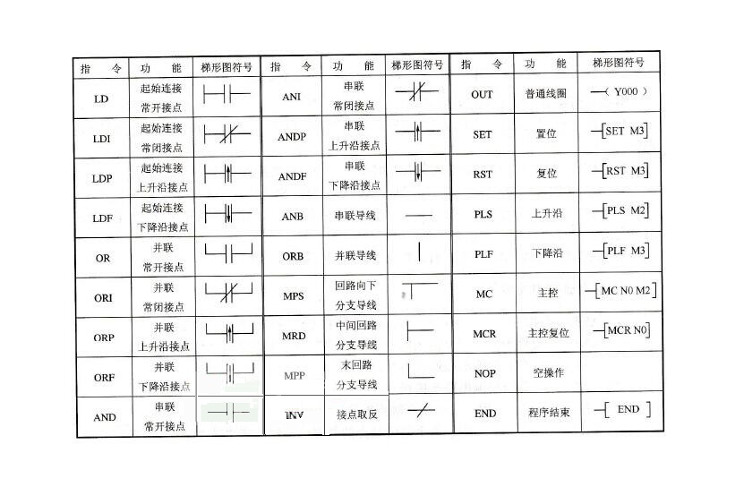
The basic logic instructions of the Mitsubishi FX series PLC.
Instruction fetch and output instruction (LD/LDI/LDP/LDF/OUT)
(1) LD (fetch instruction) An instruction to connect a normally open contact to the left bus, and each of the logic lines starting with a normally open contact uses this command.
(2) LDI (inverted instruction) A normally closed contact is connected to the left bus. Each of the logic lines starting with a normally closed contact uses this command.
(3) LDP (take rising edge command) The rising edge detection command of the normally open contact connected to the left bus is turned on for one scan cycle only when the rising edge of the specified bit device (from OFF to ON).
(4) LDF (take falling edge command) The falling edge detection command of the normally closed contact connected to the left bus.
(5) OUT (output command) The command to drive the coil is also called the output command.
Instructions for using instructions and output instructions:
1) The LD and LDI instructions can be used to input the contacts connected to the left bus, or to cooperate with the ANB and ORB instructions to implement block logic operations;
2) The LDP and LDF instructions maintain one turn-on of the scan period only when the corresponding component is active.
3) The target components of the LD, LDI, LDP, and LDF instructions are X, Y, M, T, C, and S;
4) The OUT instruction can be used continuously several times (equivalent to coil parallel). For timers and counters, a constant K or data register should be set after the OUT instruction.
5) The target components of the OUT instruction are Y, M, T, C, and S, but they cannot be used for X. Contact series command (AND/ANI/ANDP/ANDF)
(1) AND (and instruction) A normally open contact is connected in series to complete the logical AND operation.
(2) ANI (and reverse command) A normally closed contact is connected in series to complete the logical NAND operation.
(3) The rising edge of ANDP detects the serial connection command.
(4) The falling edge of ANDF detects the serial connection command.
Instructions for the use of contact series instructions:
1) AND, ANI, ANDP, ANDF all refer to the instructions that a single contact is connected in series. There is no limit to the number of series connections, and it can be used repeatedly.
2) The target elements of AND, ANI, ANDP, and ANDF are X, Y, M, T, C, and S.
3) After the OUT M101 command, driving Y4 through the contact of T1 is called continuous output.
Contact parallel command (OR/ORI/ORP/ORF)
(1) OR (or instruction) Used for parallel connection of a single normally open contact to achieve a logical OR operation.
(2) ORI (or non-instruction) is used for parallel connection of a single normally closed contact to achieve a logical "OR" operation.
(3) The rising edge of ORP detects the parallel connection command.
(4) ORF falling edge detection parallel connection instruction.
Instructions for using the contact parallel command:
1) The OR, ORI, ORP, and ORF instructions all refer to the parallel connection of a single contact. The left end of the parallel contact is connected to the LD, LDI, LDP or LPF, and the right end is connected to the right end of the corresponding contact of the previous instruction. The number of times the contact parallel command is used continuously is not limited;
2) The target components of the OR, ORI, ORP, and ORF instructions are X, Y, M, T, C, and S. Block operation instruction (ORB / ANB)
(1) ORB (block or instruction) A parallel connection between circuits in which two or more contacts are connected in series.
Instructions for using the ORB instruction:
1) When several series circuit blocks are connected in parallel, each series circuit block should start with LD or LDI instructions;
2) There are multiple circuit blocks in parallel, and if ORB instructions are used for each circuit block, there is no limit to the number of circuit blocks connected in parallel;
3) The ORB instruction can also be used continuously, but this program is not recommended. The number of times the LD or LDI instruction can be used must not exceed 8 times, that is, the ORB can only be used continuously for 8 times or less.
(2) ANB (Block and Instruction) A series connection between circuits in which two or more contacts are connected in parallel.
Instructions for using the ANB instructions:
1) When the parallel circuit blocks are connected in series, the beginning of the parallel circuit block uses LD or LDI instructions;
2) When multiple parallel circuit block connections are connected in series with the previous circuit, there is no limit to the number of times the ANB instruction can be used. ANB can also be used continuously, but like ORB, the number of uses is less than 8 times.
Set and reset instructions (SET/RST)
(1) SET (Set Instruction) Its purpose is to set and hold the target component being operated.
(2) RST (Reset command) Resets the target component being operated and keeps it clear. When the SET and RST instructions are used, when X0 is normally open, Y0 is turned ON and remains in this state, even if X0 is turned off, Y0 remains unchanged; only when X1 is normally open and closed, Y0 It turns OFF and remains. Even if X1 is normally open and closed, Y0 is still OFF.
Instructions for using the SET and RST instructions:
1) The target components of the SET command are Y, M, and S. The target components of the RST command are Y, M, S, T, C, D, V, and Z. The RST instruction is often used to clear the contents of D, Z, and V. It is also used to reset the integrated timer and counter.
2) For the same target component, SET and RST can be used multiple times, and the order can also be arbitrary, but the final performer is valid. Differential instruction (PLS/PLF)
(1) PLS (rising edge differential instruction) A pulse output of one scan period is generated on the rising edge of the input signal.
(2) PLF (falling edge differential instruction) A pulse output of one scan period is generated on the falling edge of the input signal.
The edge of the signal is detected by the differential instruction, and the state of Y0 is controlled by the set and reset commands.
Instructions for using PLS and PLF instructions:
1) The target components of the PLS and PLF instructions are Y and M;
2) When using PLS, the target component is ON only in one scan cycle after the drive input is ON, and M0 is ON only during one scan cycle when the normally open contact of X0 is turned off; when using the PLF instruction, only the use The falling edge of the input signal is driven, and the others are the same as the PLS.
Master command (MC/MCR)
(1) MC (master command) Used for the connection of the common series contact. After MC is executed, the left busbar moves to the back of the MC contact.
(2) MCR (Master Reset Command) This is the reset command of the MC command, that is, the position of the original left bus is restored by the MCR command.
In programming, it often happens that multiple coils are controlled by one or a group of contacts at the same time. If the same contacts are serially connected in the control circuit of each coil, many memory cells will be occupied, and the master control commands will be used. This problem can be solved.
The MC and MCR instructions use the MC N0 M100 to implement the left bus shift to the right, so that Y0 and Y1 are both under the control of X0, where N0 represents the nesting level, and the number of uses of N0 in the no-nested structure is unlimited; using MCR N0 Restore to the original left bus state. If X0 is disconnected, the instruction between MC and MCR is skipped.
Instructions for using MC and MCR instructions:
1) The target components of the MC and MCR commands are Y and M, but special auxiliary relays cannot be used. MC takes 3 steps, and MCR takes 2 steps.
2) The main control contact is perpendicular to the general contact in the ladder diagram. The main control contact is a normally open contact connected to the left busbar and is the master switch that controls a group of circuits. The contacts connected to the main control contacts must be commanded with LD or LDI.
3) When the input contact of the MC instruction is turned off, the integrated timer, counter, and component driven by the reset/set instruction in MC and MCR remain unchanged. For non-integrated timers and counters, the component driven by the OUT instruction will be reset, and when X0 is turned off in 22, Y0 and Y1 will be turned OFF.
4) If you use the MC instruction again in an MC instruction area, it is called nesting. The number of nesting levels is up to 8 levels, and the number is increased in the order of N0→N1→N2→N3→N4→N5→N6→N7. The return of each level is reset from the nested level with a large number by the corresponding MCR instruction. Stack instruction (MPS/MRD/MPP)
The stack instruction is a new basic instruction in the FX series for multiple output circuits for ease of programming. There are 11 memory cells in the FX series PLC, which are used to store the intermediate results of program operations, called stack memory.
(1) MPS (Pushing Instruction) The operation result is sent to the first segment of the stack memory, and the previously sent data is sequentially moved to the next segment of the stack.
(2) MRD (Read Stack Instruction) The first piece of data of the stack memory (the last pushed data) is read out and the data is continuously stored in the first segment of the stack memory, and the data in the stack does not move.
(3) MPP (Post Instruction) Reads the first piece of data of the stack memory (the last pushed data) and the data disappears from the stack, and simultaneously moves other data in the stack up.
Instructions for the use of stack instructions:
1) The stack instruction has no target component;
2) MPS and MPP must be paired;
3) Since there are only 11 stack storage units, the stack has a maximum of 11 layers.
Logical inverse, null and end instructions (INV/NOP/END)
(1) INV (reverse command) After the instruction is executed, the original operation result is inverted. The use of the counterinstruction is shown in Figure 10. If X0 is off, Y0 is ON, otherwise Y0 is OFF. When using it, it should be noted that INV cannot be connected to the bus as LD, LDI, LDP or LDF of the instruction list, nor can it be used separately as the OR, ORI, ORP, and ORF instructions in the instruction list.
(2) NOP (No-Operation Command) No operation is performed, but it takes one step. Nothing is done when executing NOP. Sometimes you can use the NOP instruction to short some contacts or use the NOP instruction to overwrite the unwanted instructions. When the PLC performs the clear user memory operation, the contents of the user memory all become empty operation instructions.
(3) END (end command) Indicates the end of the program. If the END instruction is not written at the end of the program, the PLC will execute from the first step of the user program memory to the last step regardless of the actual user program; if there is an END instruction, when the END is scanned, the execution of the program ends. Shorten the scan cycle. During program debugging, several END instructions can be inserted into the program to divide the program into several segments. After determining that the previous program segment is correct, the END instruction is deleted in turn until the debugging ends.
Stepping instructions for FX series PLC
1. Step instruction (STL/RET)
Step instructions are instructions designed for sequential control. In the field of industrial control, many control processes can be implemented in a sequential control manner. The use of stepping instructions to achieve sequential control is both convenient and easy to read and modify.
There are two stepping instructions in the FX2N: STL (step contact command) and RET (step return command).
The STL and RET instructions can only have a step function in conjunction with the stater S. For example, STL S200 represents a state normally open contact, called an STL contact, and its symbol in the ladder diagram is -|| ||- , which has no normally closed contact. We use each state machine S to record a step, for example, STL S200 is valid (ON), then enter the step indicated by S200 (similar to the main switch of this step), start the work done in this stage, and judge the entry. Whether the one-step condition is met. Once the end step signal is ON, the S200 is turned off to the next step, as in step S201. The RET instruction is used to reset the STL instruction. After executing RET, it will return to the bus and exit the step state.
2. State transition diagram
A sequential control process can be divided into several phases, also called steps or states, each with different actions. When the transition condition between two adjacent states is satisfied, the conversion is implemented, that is, the transition from the previous state to the next state is performed. We use a state transition diagram (function table diagram) to describe this sequence control process. Each state is recorded with a stater S, which is a transition condition. When X1 is ON, the system changes from S20 state to S21 state.
Each step in the state transition diagram contains three contents: the content driven by this step, the transition condition, and the conversion target of the instruction.
Step drive Y0. When X1 is active ON, the system changes from S20 state to S21 state, X1 is the conversion condition, and the conversion target is S21 step.
3. Instructions for use of step instructions
1) The STL contact is a normally open contact connected to the left busbar. When an STL contact is turned on, the corresponding state is an active step;
2) The contact connected to the STL contact applies the LD or LDI command, and only returns to the left bus after the RET is executed; 3) the STL contact can be driven directly or through other contacts to drive Y, M, S, T, etc. The coil of the component;
4) Since the PLC only executes the circuit block corresponding to the active step, the double coil output is allowed when the STL instruction is used (the sequence program can drive the same coil multiple times in different steps);
5) The MC and MCR instructions cannot be used in the circuit block driven by the STL contact, but the CJ instruction can be used. 6) The STL instruction cannot be used in the interrupt program and subroutine.
Solar Powered Pump,Solar Water Pump,Solar Pump,Solar Powered Water Pump
Wuxi Shengda Yukun Energy Development co.,Ltd , https://www.xlite-solarlight.com