Foreword:
Compared to helicopters, multirotor aircraft such as quadcopters offer a simpler mechanical structure, more flexible control, and better stability. They are smaller in size and have greater payload capacity. The complex mechanical design of helicopters is replaced with electronic circuits and algorithms, making quadcopter development more accessible and popular.
The core software of a quadcopter includes attitude fusion and control algorithms, while the hardware consists of an MCU and sensors.
First, I'll explain the attitude fusion algorithm. This process combines 3-axis acceleration, 3-axis angular velocity, and 3-axis magnetic field data into a quaternion, which is then converted into Euler angles. These angles (Yaw, Pitch, Roll) are used to control the aircraft's orientation. I use Madgwick’s AHRSUpdate and IMUUpdate algorithms, which are efficient and widely used. While IMUUpdate only fuses accelerometer and gyroscope data, it requires complementary filtering for magnetometer correction, which can cause issues when yaw crosses 0 degrees. AHRSUpdate solves this problem but may be affected by strong external magnetic fields, leading to loss of control.
The sensor I used is the Invensense MPU9150, which integrates an accelerometer, gyroscope, and magnetometer with built-in DMP for attitude fusion. However, it’s not easy to use. The MCU is the Gigadevice GD32F103 series, chosen for its cost-effectiveness and compatibility with STM32. Future upgrades might include GD32F107 or GD32F2xx for camera integration, and even GD32F4xx for better floating-point performance due to the high computational demand of my algorithms.
Quadcopters are fun, and I’ve completed the first step: attitude fusion. Next, I’ll focus on selecting the right frame, ESCs, motors, propellers, writing PID code, and debugging parameters. I also plan to add various peripherals later. Keep going, stay patient, and keep learning.
Currently, I implement functions like AHRSUpdate, gyroscope zero calibration, accelerometer filtering, and magnetometer plane calibration. In the future, I aim to improve accuracy with ellipsoid fitting, temperature compensation, and more.
Part 1: Hardware
1. Sensor: MPU9150 (Invensense), integrating accelerometer, gyroscope, and magnetometer. It has a built-in DMP, but only fuses accelerometer and gyroscope. It’s compact and reliable, though less accurate than using separate sensors.
2. MCU: GD32F103CB (Gigadevice), ARM Cortex-M3 core, 108MHz clock speed. It’s cost-effective but has limited timers. Later versions like GD32F107VCT6 will be considered.
3. Power chip: TLV70233DBVR (TI LDO), 2-6V input, 3.3V output, but expensive.
4. Serial port: MAX3232 for easy debugging.
5. USB power supply: 5V output.
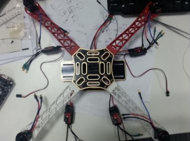
6. Frame, ESCs, motor, battery, and propeller have been purchased, and the image shows a typical setup.
Part II: Software
1. Keil uVision 4.1.0 with RealView MDK-ARM v4.12.
2. Drivers: Official MPU6050 drivers from Invensense.
Before diving into the algorithm, let me show some diagrams. Here’s the system initialization sequence: initialize the MPU, set sensors, configure ranges, FIFO, sampling rate, load DMP, set gyroscope axes, enable DMP, self-calibrate, start attitude fusion.
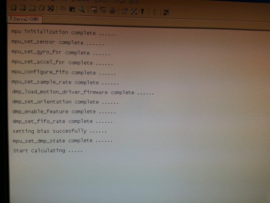
Figure 2 shows the final Euler angles from the quaternion. Yaw is the heading angle, Pitch is the elevation, and Roll is the bank. When the plane is level, the nose points 37 degrees west of north.
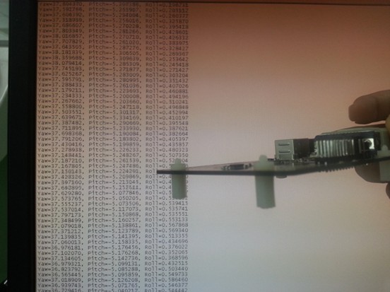
Figure 3 shows the plane level, with the nose pointing north and 25 degrees down.
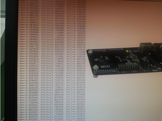
Figure 4 shows the nose pointing north, level, with the right wing tilted down 23 degrees.
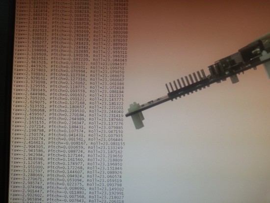
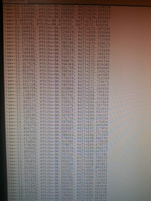
Figure 5 highlights the singularity of Euler angles. When Pitch is +90°, the aircraft becomes uncontrollable, and the Roll axis changes abruptly.
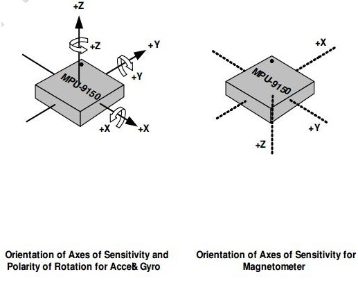
Part III: Axis Definition
The axis definition affects the initial quaternion and Euler angle calculations. The right-hand rule must be followed. For example, if the x-axis is Roll, y-axis is Pitch, and z-axis is Yaw, the rotation order matters. I defined the axes carefully to ensure consistency with the algorithm.
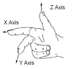
Here’s how to define a proper axis direction. The right-hand rule ensures that the rotation direction matches the coordinate system. The figure below shows the original [xyz] and rotated [-yxz].

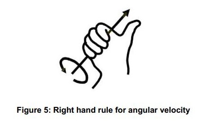
This diagram explains how to determine the positive rotation direction. Hold the axis with your right hand, thumb points forward, fingers curl in the positive rotation direction. This applies to both the initial quaternion and the final Euler angle calculation.
The axis configuration in my program is shown below, without any modifications.
Part IV: Algorithm
First, calibrate the accelerometer and gyroscope. I use the internal self-calibration of the MPU9150. For the magnetometer, I follow a separate calibration procedure.
Next, initialize the quaternion. Common definitions are Roll around x, Pitch around y, and Yaw around z. I use a different definition for comparison and clarity.
After processing the accelerometer and magnetometer data, I calculate the initial Roll, Pitch, and Yaw. A negative sign is added to ensure correct rotation direction.
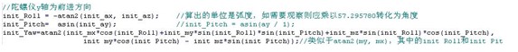
The Yaw direction may need verification. For details, refer to the attached ST electronic compass documentation.
Then, the initial quaternion is calculated based on the Euler angles. The rotation order (ZXY) is crucial here. The formula for the quaternion is derived accordingly.

Finally, after applying the AHRSUpdate algorithm, the Euler angles are recalculated. The rotation order (ZXY) and axis definitions are key to accurate results.
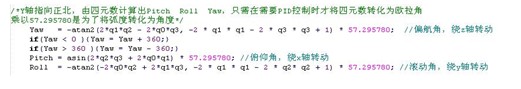
When the system is powered on and stationary, the data fluctuates within 1 degree, showing no drift. Further tuning is needed once the quadcopter is airborne.
Summary:
In my code, 0° is defined based on the sensor axes. At 108MHz, the delay and serial functions need adjustment to prevent I2C communication failures. For detailed steps, refer to the forum post at http://bbs.21ic.com/iclist-182-1.html.
Thank you to everyone who supported me along the way.
OREMA deep cycle batteries are known for their exceptional performance and reliability in long duration cycling applications. They offer a range of options, including the UND series of AGM Deep Cycle Batteries, UNG series of GEL batteries, deep cycle batteries, and Tubular Batteries.
The UND series of AGM deep cycle batteries are designed to provide enhanced performance and reliability. They are equipped with high density active materials plates and a specialized paste formulation. This unique combination allows the battery to have a longer service cycle life without compromising its overall lifespan. These batteries are perfect for applications that require continuous and reliable power supply over an extended period.
The UNG series of GEL batteries are another option offered by OREMA. These batteries are known for their excellent reliability and durability. The gel electrolyte used in these batteries ensures better resistance against deep discharge, making them ideal for applications that require frequent cycling. The UNG series batteries are designed to provide consistent and reliable power even in demanding conditions.
OREMA also offers a range of deep cycle batteries that are specifically designed for long duration cycling applications. These batteries are equipped with high-quality materials and advanced technology to ensure optimal performance and longevity. They are capable of withstanding repeated deep discharge cycles without compromising their overall performance. These deep cycle batteries are perfect for applications such as solar power storage, electric vehicles, and marine applications.
Additionally, OREMA offers Tubular batteries, which are known for their superior performance and reliability. These batteries are constructed with tubular positive plates that provide excellent resistance against corrosion and enhance the overall lifespan of the battery. The Tubular batteries are designed to deliver consistent and reliable power over a long period, making them suitable for applications that require sustained cycling.
In conclusion, OREMA deep cycle batteries, including the UND series of AGM deep cycle batteries, UNG series of GEL batteries, deep cycle batteries, and Tubular batteries, are engineered to provide enhanced performance and excellent reliability in long duration cycling applications. With their high density active materials plates and specialized paste formulation, these batteries offer a longer service cycle life without compromising their overall lifespan. Whether it's for solar power storage, electric vehicles, or marine applications, OREMA deep cycle batteries are a reliable choice.
General Future:
5-20 years design life(25℃)
Non-spillable construction
Sealed and maintenance-free
Excellent recovery from deep discharge
High density active materials plates
Longer Life and low self-discharge design
Standards:
Compliance with IEC, BS, JIS and EU standards.
UL, CE Certified
ISO45001,ISO 9001 and ISO 14001 certified production facilities
Application:
Solar and wind power system
Communication systems
Uninterruptible power supplies
Golf cars and buggies
Alarm and security system
Electric toy and wheelchairs, etc.
Deep Cycle Agm Battery,Agm Battery Deep Cycle,Solar Battery Deep Cycle,Deep Cycle Solar Battery
OREMA POWER CO., LTD. , https://www.oremapower.com