introduction
All electronic products sold worldwide must be carried out before going public EMI / EMC tests prove that they do not interfere or are not interfered with by other devices. For testing purposes, these products can be divided into two categories: active radiation products and non-active radiation products, such as cellular phones and walkie-talkies that actively radiate energy, while televisions, computers, and laptops should not radiate energy.
This article refers to the address: http://
The type of product is different from the test organization, and the test requirements for EMI/EMC are also different. However, EMI/EMC testing can be roughly divided into two categories:
- Radiation: This test limits the amplitude and frequency of a signal radiated or conducted by a product so that it does not interfere with other products.
- Sensitivity (also known as immunity): This test illustrates the product's ability to suppress radiation by limiting the amplitude and frequency of radiated and conducted signals that interfere with proper operation of the device.
As mentioned above, EMI can be divided into conduction interference and radiation interference. Since all EMI radiation is generated by current, these two types of interference are related to each other. But not all currents produce radiation. Therefore, we must first analyze and suppress the radiation interference problem, and then deal with the conduction interference problem. For both types of interference, radiated interference is more difficult to predict and suppress. Therefore, it is the main reason for the failure of EMI testing of most non-active radiation products. Here, we will focus on how to solve the radiated interference problem of the audio/video interface that is ubiquitous in many products.
A variety of methods can be used to meet the conditions defined in the EMI/EMC regulations. But most of these methods can be classified into two categories: shielding and filtering. In practical products, these methods are combined with specific applications to achieve a comprehensive EMI solution. For example, in most products, a metal housing is used to shield the radiation while LC or RC filters are used to reduce conducted interference on the input/output lines. In addition, a jitter clock can be used to spread the spectrum range to reduce filtering or shielding requirements for specific applications.
When the EMI performance of the product basically meets the requirements, it will be taken to the certification laboratory for formal testing. If the product passes the test, it can be placed on the market; not passing the test means there is a problem. Even a small change can take a long time to solve a problem. This may delay the time-to-market of the product, as both international and domestic markets require that the product pass the EMI/EMC compatibility test1. As a result, EMI design often sacrifices the video performance of the product to ensure it passes the test. In modern designs, the physical size and cost of the components required for EMI testing need to be considered, and at the expense of video performance.
The shrinking size of modern audio/video analog interfaces, while the high performance expectations, poses a serious challenge to the design. To solve this problem, first find out the source of most EMI/EMC test failures; then explore possible solutions.
Source of test failure
EMI/EMC test failures typically occur at the weakest point in product design—signal (and interference) from or to the shielded and filtered mechanism. In the audio/video interface, the weakest point is the cable that connects the devices, which is equivalent to the antenna. For computers, the cable that connects the display and speakers to the PC is the weakest link, and it often causes EMI/EMC problems. We might think that only high-bandwidth video interfaces will cause this kind of problem, and low-frequency audio interfaces will not have this problem. This is true when all amplifiers use Class A audio amplifiers. However, the currently used high-efficiency class D amplifiers 2 have high-frequency switching signals, and EMI problems can occur if proper filtering and shielding are not performed.
In the past, large external filters and/or shielded cables could be used to solve these problems. But these methods not only increase the cost, but also affect product performance and increase product size. As these products continue to shrink in size and become the current audio/video player, EMI/EMC solutions must reduce product size while maintaining or even improving system performance. To achieve this, a graphics and video interface such as the MAX9511 and the MAX9705 have been developed. Small devices such as Class D audio amplifiers that provide excellent EMI performance. To show how this improvement can be achieved, look at the audio and display interface 3 of a regular PC and the EMI performance provided by these tiny devices. First, we should understand the various EMI issues that must be addressed in audio/video interface design, and then give a solution to these problems.
Video and EMI
The video format commonly used by computers, which is what we call "graphics", is different from the video format of TV. Computer video has red, green, and blue (R, G, B) analog video signals, as well as logic signals consisting of line, field sync, and DDC 5 , all of which have fast rise/fall times. Video connectors typically use a high-density, ultra-D-type connector for connecting the display to a PC ( Figure 1 ). Although this solution combines video signal shielding (coaxial) and common mode choke (CMC) to reduce radiated and conducted EMI, it is necessary to add filtering to ensure EMI requirements are met. In broadcast video applications, similar filtering measures are employed to eliminate aliasing artifacts in television images. However, this is not possible in graphics video because the purpose of graphics video is to reproduce the checkerboard pattern of "on" and "off" pixels at the highest possible resolution. Therefore, in order to achieve the best display performance, we hope that the larger the bandwidth, the better. However, in practical applications, EMI and video performance must be weighed, so video bandwidth is sacrificed. For multi-signal video interfaces, multiple factors need to be weighed.
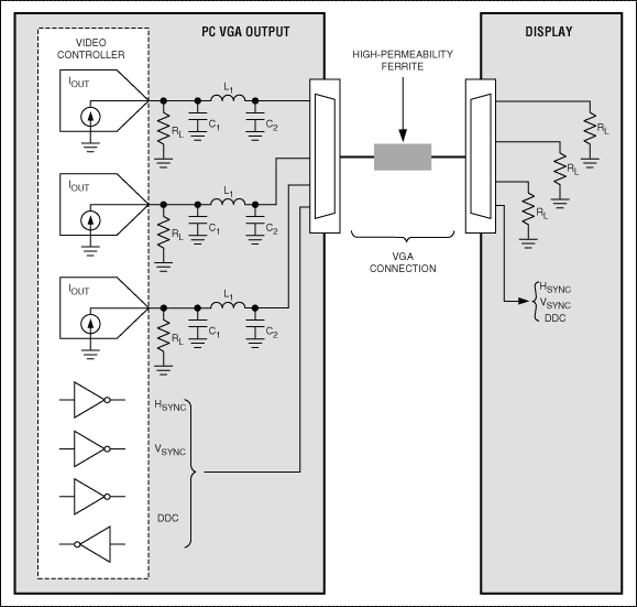
Figure 1. Typical VGA connection and video signal that produces radiated EMI
For example, when filtering a video signal, a time delay occurs, and if the delay time of each video channel (R, G, and B) cannot be precisely matched, a color edge effect is produced. To avoid this phenomenon, it must be closely controlled channel group delay and group delay matching 6. RGB video is extremely susceptible to these parameters 7 . For best performance, the group delay must be consistent with the frequency, and the minimum group delay match between channels must be kept within ±0.5 pixel time. If the match can be so precise, the sync signal must also track the channel delay to properly display the image frame. After doing this, you need to solve the multi-video resolution problem supported by the PC.
In this application, it is very difficult to achieve optimal performance with a fixed frequency filter. If we design a filter to suppress EMI at the lowest resolution, the filter's stopband will be intervened in the signal bandwidth of the higher resolution format, affecting higher resolution video performance. If you design a filter for the highest resolution format, you may not be able to meet EMI requirements. Obviously, the best solution is to use a "tunable" filter with a frequency response that tracks the display resolution, but this approach adds cost and can also increase product size. In addition, the effects of synchronous and DDC drivers' fast rise/fall times on EMI performance are also important. Therefore, in any complete EMI solution, methods that delay these rise/fall times must be included. There are also some legacy issues, such as video DAC load detection to meet plug-and-play requirements.
The MAX95118 does all of this. As shown in FIG. 2, it is given a high-resolution graphics card The MAX9511 uses the output, an LC filter scheme, and the EMI characteristics of the raw output without filtering.
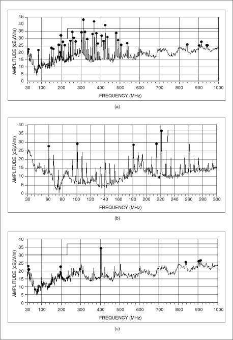
Figure 2. Radiated EMI in three cases: a) no filtering, b) passive LC filter, c) MAX9511
Complete EMI Solution (MAX9511)
The MAX9511 graphics video interface shown in Figure 3 provides a matched, three-channel tunable EMI filter for RGB video with resolution ranging from VGA to UXGA with skew between channels less than 0.5ns. The slew rate adjustment function is implemented by changing the resistance of a single resistor (R x ). Corresponding to the different VESA resolutions and their sampling clock ranges, Table 1 lists the relationship between resistance and slew rate. In the circuit of Figure 4 , the potentiometer MAX54329 controlled by I 2 C provides 32 stages of filter control. However, as can be seen from Table 1, only three or four levels of control are required in most applications. In the final EMI/EMC test, the EMI performance of a product can be improved without any mechanical or electrical changes.
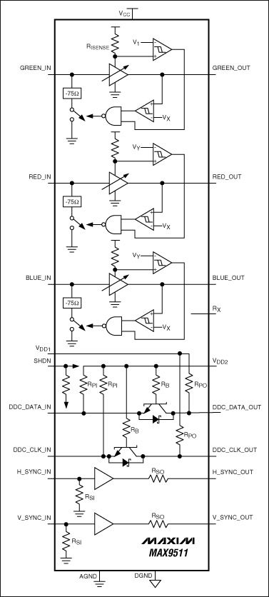
Figure 3. MAX9511 VGA interface with EMI suppression
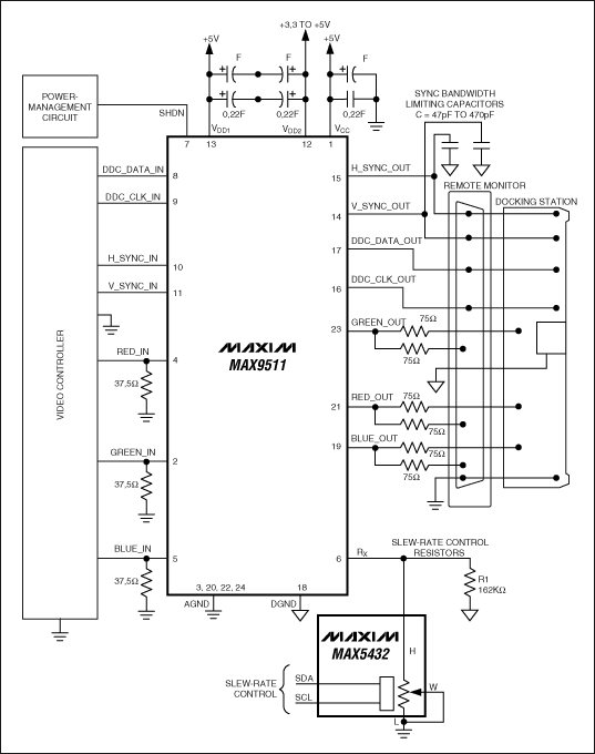
Figure 4. The MAX9511 drives multiple outputs. Adjustable filtering is controlled by the MAX5432 I 2 C digital potentiometer.
Table 1. Swing Rate, Bandwidth, and Rx Resistance of the MAX9511
R x (k  ) ) | |||
| Slew Rate (V/ms) | Pixel Clock Frequency (MHz) | VESA Resolution | |
| 7 | 1408 | 160 to 230 | UXGA (1600 x 1200) |
| 10 | 1255 | 160 to 230 | UXGA (1600 x 1200) |
| 12 | 1050 | 100 to 150 | SXGA (1280 x 1024) |
| 15 | 810 | 100 to 150 | SXGA (1280 x 1024) |
| 20 | 613 | 45 to 95 | XGA (1024 x 768) |
| 25 | 470 | 45 to 95 | XGA (1024 x 768) |
| 30 | 368 | 45 to 95 | XGA (1024 x 768) |
| 35 | 298 | 35 to 50 | XGA (1024 x 768) |
| 40 | 255 | 35 to 50 | SVGA (800 x 600) |
| 45 | 203 | 35 to 50 | SVGA (800 x 600) |
| 50 | 158 | 25 to 30 | VGA (640 x 480) |
| > 50 | < 150 | < 25 | QCIF |
RGB video output is low impedance (Z OUT < 1
 ), plus 75
  The reverse termination resistor provides 45dB to 50dB isolation between the remote monitor and the docking station. Previously, when driving two different outputs in this way, a switch was needed to avoid connecting the LC filter output to a longer unterminated branch. As shown in Figure 4, it can be seen how the MAX9511 senses the output load, and whether the output load is connected or not will cause a significant change in the impedance of the DAC termination of the input. The video controller that drives the RGB input can detect this impedance change, and if the load is not connected, turn off the video output and sync output by turning off the pin. The DDC is always in a normally open state to support plug and play, and the driver also has a level shifting function that converts the low voltage controller level to a standard 5V interface level. Synchronous drive has 50
  (Typical) Output impedance, an external capacitor can be used to limit the edge slew rate (Figure 4). Synchronous jitter (without capacitance) is typically less than 0.5 ns. Video performance also includes: +6dB gain, 50dB SNR, 0.036% linearity error and less than 1% overshoot/undershoot (with excellent damping response).
 Audio and EMI
The audio interface needs to solve a series of different problems to achieve efficiency and performance without generating EMI. In portable applications, we want to maximize battery life without expecting inefficient designs to generate heat, so Class D amplifiers are widely used. The problem is that Class D amplifiers use PWM for high efficiency, which is very similar to switching power supplies. When an unshielded speaker cable is used to connect to the output, the cable radiates EMI like an antenna. Although the clock frequency (typically 300kHz to 1MHz) is higher than the audio spectrum, it is a square wave with a large number of harmonic components. The filter used to filter out the harmonic components is relatively large in size and costly. In laptop computers and other portable applications, due to size, this is not a viable solution 10.
A general design topology cannot solve both problems at the same time. To maximize output audio power, portable applications use a bridge-tied load (BTL) connection where both wires are effectively driven ( Figure 5 ). In a Class D amplifier, the comparator is used to monitor the analog input voltage and compare the input voltage to a triangular wave. When the amplitude of the triangular wave is higher than the audio input voltage, the comparator flips while the inverter produces a complementary PWM waveform to drive the other side of the BTL output stage. Due to this BTL topology, the output filter actually requires twice as many components as the single-ended audio output: two inductors (L1 and L2) and two capacitors (C1 and C2). These two inductors need to handle the peak output current, so they are large in size and take up most of the space.
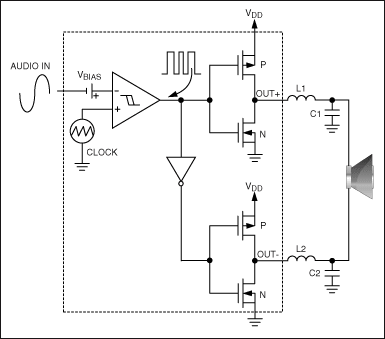
Figure 5. Active radiation limiting techniques used in a typical Maxim Class D audio amplifier.
Class D amplifiers use the coil inductance and discrete capacitance of the speaker to form a filter, eliminating the need for additional filters. Since the speaker cable still radiates a significant amount of energy, this method is limited to the internal speakers. One approach is to change the switching process so that the amplifier remains efficient while reducing EMI, requiring only a small filter. To achieve this object, the clock frequency can be modulated to reduce the energy per hertz of bandwidth 11. This method is called clock spread spectrum modulation 12 , or clock frequency jitter. However, the effectiveness of spectrum spreading has a certain range. The typical radiation spectrum shown in Figure 6 illustrates the effect of this technique.
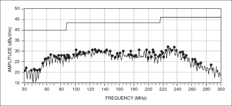
Figure 6. The MAX9705 radiation data from the MAX9705EVKIT (12-inch unshielded twisted pair) demonstrates the benefits of spread spectrum modulation.
For devices that only provide spread-spectrum modulation, when the output power is higher than a few hundred milliwatts, a speaker cable that is longer than a few inches will radiate too much energy. Increasing the clock frequency at this time does not help, as the frequency increases, the output spectrum of the Class D amplifier will decrease. However, the speaker connections become as efficient as the antenna, offsetting any performance improvements. To further improve EMI performance, it is required to change the PWM waveform used by the Class D amplifier itself. This can be achieved using a specific method called active radiation limitation.
The active radiation limiting circuit sets the minimum pulse width of the amplifier, while the design in Figure 5 does not limit the maximum boundary. Recombination overlap, rise / fall time, and clock frequency, power generated 13 may be limited in a spectrum given output power level during operation. The goal is to reduce the spectrum to a level that allows the device to meet radiated limits without any external filtering and with up to 24in external speaker connections.
We also want to get good audio performance, which requires a peak power output of more than 2W. At the same time, it is desirable to minimize heat and maximize battery life. Therefore, the device is required to achieve high efficiency under a low voltage single power supply, and has a low power shutdown mode suitable for earphone applications. THD+N must be low, the SNR must be high, and with click suppression, the input must be compatible with single-ended or differential inputs. The MAX9705 not only does the above tasks, but it also has more features, as you will see below.
Active Radiation Limit (MAX9705)
Maxim's active emissions limiting Class D amplifiers employed as shown in FIG. It is not clear from the figure how the switch operates. With the careful design of the driver circuit and zero dead time control, the MAX9705 Class D amplifier can exceed 85% efficiency. The unique, proprietary spread-spectrum modulation mode flattens the spectral components and reduces the EMI emissions from connecting cables and speakers. In stereo or multi-channel applications, the sync input locks the clock frequency of all amplifiers to the 800kHz to 2MHz universal clock range, minimizing intermodulation, which can result in intermodulation of multiple independent clock sources. Maxim's Class D audio amplifiers combine two unique technologies: spread spectrum modulation and active emission limiting. Up to 24 in unshielded speaker connections can be connected in a “no filter†condition, while radiated interference remains within the EMI limits specified in FCC Part 15 ( Figure 8 ).
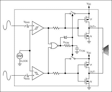
Figure 7. The MAX9705 Class D amplifier internally generates sawtooth waves and provides differential inputs. If a single-ended input is used, a differential input can be generated internally.
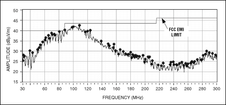
Figure 8. Radiation data when the MAX9705 is connected to a 24in unshielded twisted pair in spread-spectrum modulation mode
In addition to EMI, the audio performance is also very good, THD+D is 0.02% at 1W, 1% at 2.3W, and 90dB SNR. The input can be either a differential input or a single-ended input that provides +6dB, +12dB, +15.6dB, or +20dB fixed gain for any application (Figure 7). Power consumption is minimized in shutdown mode. In addition, the sync input allows the MAX9705 to deliver mono, stereo or multichannel high-performance audio that meets EMI emissions requirements when connected to external speakers without a filter.
Conclusion
The MAX9511 and MAX9705 represent advanced technologies for EMI/EMC control. Applying these devices to the product can effectively reduce EMI. There is no need to rely on large external filters and shielding to increase cost and size as before, and these devices use today's most advanced technology to ensure electromagnetic compatibility and performance.
Robot Mower Charger,Robot Lawn Mower Adapter,Robot Lawn ,Cutting Blade
Robot Lawn Mower,Robot Humidifier Co., Ltd. , http://www.zd-machinery.com