1 Introduction
With the development of science and technology, the field of human research activities has expanded from land to seabed and space. The use of mobile robots for space exploration and development has become one of the main means of developing space resources in the world's major technologically advanced countries in the 21st century. Research and development of lunar exploration mobile robot technology will greatly promote the research of related cutting-edge technologies including mobile robots.
The mobile robot is a robot system that can sense the external environment and its own state through sensors, and realize the autonomous movement of the target in an obstacle environment, thereby completing a certain operation function. In recent years, mobile robots have become more and more widely used in industrial, agricultural, medical, aerospace and human life, making it a hot research topic in international robotics. Since the 1990s, with the development of high-level environmental information sensors and information processing technology, highly adaptive mobile robot control technology, and planning technology in the real environment as a symbol, a higher level of research on mobile robots has been carried out. At present, mobile robots, especially autonomous robots, have become an active research field in robotics.
The wheeled moving mechanism has the advantages of fast moving speed, high energy utilization rate, simple structure, convenient control and the ability to learn from the mature automobile technology, but the off-road performance is not strong. However, with the emergence of various wheel chassis, such as NASDA's six-wheel flexible chassis lunar rover LRTV, Russia's TRANSMASH six-wheel three-body flexible frame mobile robot Marsokohod, the US CMU six-wheel three-body flexible robot Robby series and the US JPL The Rocky series of six-wheel rocker-suspended planetary rover has greatly increased the off-road capability of wheeled robots and is comparable to legged robots. As a result, the focus of research on robotics has shifted to the wheeled mechanism. In particular, Japan recently developed a unique five-point suspension structure Micros, which has superior off-road capability compared to legged robots. Less than [6-8].
The wheel structure can be divided into two-wheel mechanism, three-wheel mechanism, four-wheel mechanism, six-wheel and multi-wheel mechanism according to the number of wheels. The structure of the two-wheel moving mechanism is very simple, but it is very unstable at rest and low speed. The three-wheel mechanism is characterized by an easy mechanism, and the center of rotation is on a straight line connecting the two drive wheels, and a zero radius of gyration can be realized. The four-wheel mechanism has basically the same motion characteristics as the three-wheel mechanism, and the movement is more stable due to the addition of one support wheel. The common feature of the above-mentioned wheeled moving mechanisms is that all of their wheels can only be fixed on one plane during driving, and cannot be adjusted up and down. Therefore, the ground applicable ability is poor. The general six-wheel mechanism is mainly to improve the ground adaptability of the mobile robot, and the structure of the rocker is improved. The rocker arm structure is added, so that the wheel can be adjusted up and down according to the height of the terrain during the driving process, thereby improving the movement. The off-road capability of the robot.
2 robot body structure design
The main structure is the main structure of the robot, which includes the control system, four drive motors and some sensors. The sensors include infrared sensors, pressure sensitive sensors, sound sensors and the like to serve as the robot's eye, tactile and auditory functions. The structure is mainly a box structure, in which the motor and system hardware are placed as needed. The main structure is shown in Figure 1.
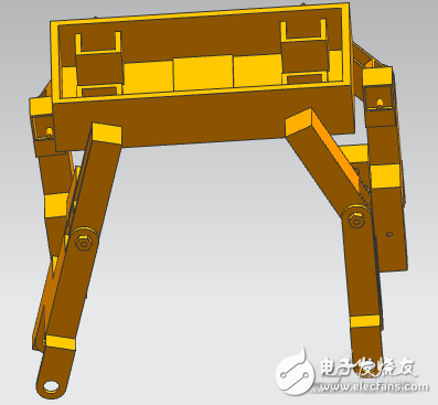
Figure 1 robot body mechanism diagram
The entire body in Figure 1 is the outer casing without any sensors and devices. The four small boxes are the motors that control the upper limbs. The holes in the side are used to pass the wires, and the middle of the large box is the board on which the control system is placed. After the entire spare parts are placed, a plate can be added on top to protect the internal components. According to my assumption, other functions can be added above the main body based on this robot. The main body is 1.5 meters wide, 0.5 meters high and 0.3 meters high.
For the lower limbs, since the Mecanum wheel can move in all directions, there is no need to join the joints, but it is necessary to add a brake system to ensure timely parking and no rolling when using the leg function, and at the joint between the lower limbs and the tire. Design the platform to discharge the electric machine so that it drives the tire to rotate. One tire corresponds to one motor so that it can control the complex movement such as direction by changing the speed of each tire.
In addition to the structure of the upper limbs, the lower limbs have two more box structures on the side, and the lower part is wider to connect with the tires. The upper box is used to install a small motor, which is connected to a shaft through two coaxial holes at the upper end of the lower limb to control the rotation of the lower limb around the upper limb, and the hole at the upper end of the box is used for passing the wire. The lower case is the motor that stores the control tires, and the space on the right side is used to place the gears and the through holes to fix the gears. Two vertical coaxial holes in the lower limbs are also used to pass the wires. The total length of the lower limbs is about 1 meter, and the width of the lower limbs is about 20 cm.
3-wheel movement principle
The principle of wheeled movement is mainly the movement principle of the Mecanum wheel.
The Mecanum Wheel is a patent of the Swedish company McNaum. This omnidirectional movement is based on the principle of a central wheel having a plurality of axles located around the wheel that convert a portion of the wheel steering force to a wheel phase force. Depending on the direction and speed of the respective wheels, the final synthesis of these forces produces a resultant force vector in any desired direction to ensure that the platform can move freely in the direction of the final resultant force vector without changing the direction of the wheel itself. . There are many small sticks distributed diagonally on its rim, so the wheels can slide laterally. The busbar of the small roller is very special. When the wheel rotates around the fixed wheel axle, the envelope of each small roller is a cylindrical surface, so the wheel can continuously roll forward. The Mecanum wheel is a compact, sporty and versatile wheel. With four of these new wheels combined, it is more flexible and convenient to achieve all-round mobility.
McNahm looks like a helical gear, the teeth are rotatable drum rollers, the axis of which is at an angle a to the axis of the wheel. This special structure allows the wheel body to have three degrees of freedom: rotation about the axle and translation in the direction perpendicular to the axis of the roller and rotation about the point of contact between the roller and the ground. Thus, while the drive wheel has active drive capability in one direction, the other direction also has free-moving (passive movement) motion characteristics. The circumference of the wheel is not made up of ordinary tires, but rather a number of small rollers are distributed, the axes of which are tangent to the circumference of the wheel and the drum is free to rotate. As the motor drives the wheels to rotate, the wheels advance in a normal manner in a direction perpendicular to the drive shaft while the rollers around the wheels are free to rotate along their respective axes. Figure 2 shows the various structures and motion parameters of the Mecanum wheel.
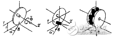
Figure 2 Definition of the motion parameters of the Mecanum wheel
4 servo control system design
The motion control system of the mobile robot is the actuator of the robot system, which plays an important role in accurately completing the tasks of the system, and sometimes can also be used as a simple controller. The elements that make up the robot motion control system are: computer hardware system and control software, input/output devices, drivers, and sensor systems. The relationship between them is shown in Figure 3.
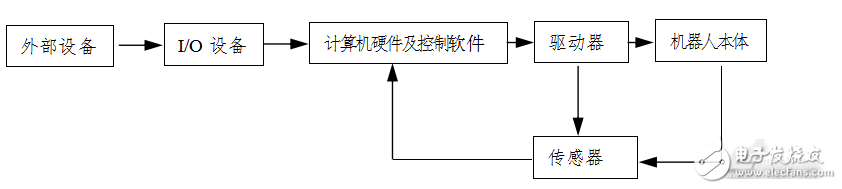
Figure 3 Robot control system components
4.1 Research on Mobile Robot Control System
(1} Mobile robot architecture. The distributed intelligent structure can improve the real-time and robustness of the mobile robot, and reduce the size and self-weight of the mobile robot, making the robot more portable and flexible.
(2) Sensor technology in the control system. The mobile robot sensor technology mainly detects and processes the position and direction information of the robot itself and the external environment information. Obtaining real and effective environmental information is a guarantee for the control system to make decisions. The commonly used sensors are divided into internal sensors and external sensors. Internal sensors mainly include: encoders, line accelerometers, gyroscopes, magnetic compasses, etc. External sensors mainly include: visual sensors, ultrasonic sensors, infrared sensors, contact and proximity sensors.
(3) Multi-sensor information fusion technology of the control system. Multi-sensor information fusion is to synthesize the incomplete information of the local environment provided by sensors distributed in different locations, eliminating the possible redundancy and contradiction between multiple sensors, to reduce its uncertainty and form a relative to the system environment. A consistent and perceptual description that improves the speed and correctness of intelligent system decisions and planning while reducing decision risk.
(4) Development technology of the control system. Focus on open, modular control systems. The standardization of mobile robot controller architecture and network controllers have become research hotspots. Programming technology further improves the operability of online programming. The more friendly human-machine interface for off-line programming, the further promotion of natural language programming and graphical programming are also the focus of future research.
(5) Motion control technology. Robot movement must be fast enough, controlled and safe, avoiding static and dynamic obstacles. Trajectory tracking, path tracking and point stabilization are the three basic problems of mobile robot motion control.
(6) Intelligent technology of the control system. The intelligent features of the control system include knowledge understanding, induction, inference, reaction, and problem solving. Areas of interest include image understanding, processing and understanding of speech and text symbols, and the expression and acquisition of knowledge. Intelligent control methods often use neural networks and fuzzy control methods, but the former is often accompanied by high requirements for storage capacity and computing speed. This has a certain gap with the requirements of high-speed and high-precision motion control of mobile robots. Therefore, the fuzzy control method is controlled by robots. The aspect has a big advantage.
According to the design requirements of the mobile robot control system, combined with the system function and characteristics of the robot, according to the modular design idea, the overall design scheme of the robot control system is proposed. As shown below:

Figure 4 control system overall plan
Control system overall design
The solution is based on the ATmega128 chip and is modularized. The functions of each sub-module are:
(1) Microprocessor module: It is the core of the control system, including the microcontroller and its related peripheral circuits mainly processing various information and data, and coordinating the various functional modules in the system to complete the predetermined tasks;
(2) Drive module: control the scheduled tasks of the steering gear and sensor module in the robot system; realize the control of the speed and position of the steering gear, and complete the actions of forward, backward, straight, turn, obstacle avoidance, grabbing, etc.;
(3) Sensor module: There are sensors such as speed, position, distance, sound, etc., which are mainly responsible for the detection of obstacles and sounds during the movement of the mobile robot;
(4) Power module: responsible for the power supply of the entire mobile robot, enabling the system to move offline, mainly composed of 12V battery and related voltage regulator circuit;
(5) Serial communication module: serial communication with the host computer according to the RS232 communication standard;
(6) JTAG debugging: online programming and debugging simulation can be realized.
3.2 Robot drive system
At present, DC motors, stepping motors and steering gears are more common in the motion control of robots. For my problem, a motor that can control speed is used as a Mecanum wheel. It also requires a motor that can be precisely controlled and can be used as a leg joint. After I initially estimated that the motor speed is not very large, if a DC motor is used, the speed reducer should be configured due to the influence of the speed and torque, and the angle cannot be controlled. If you are using a stepper motor, you need to configure the drive. In order to meet the control requirements of the system, considering the economy, I am going to use the Dynamixel series AX-12 servo. It is a robot-specific servo motor. It can not only accurately control the angle, but also control the joint angle; it can also be set to the infinite rotation mode by software and used as a wheel.
3.3AX-12 digital steering gear overview and characteristics
The steering gear is a position servo drive for control systems that require constant angle changes and can be maintained. The working principle is that the control signal enters the signal modulation chip from the channel of the receiver to obtain a DC bias voltage. It has a reference circuit inside, which generates a reference signal with a period of 20mS and a width of 1.5ms. The obtained DC bias voltage is compared with the voltage of the potentiometer to obtain a voltage difference output. Finally, the positive and negative voltage output of the voltage difference to the motor drive chip determines the forward and reverse of the motor. The AX-12 servo is an intelligent, modular power unit consisting of a microprocessor, a precision DC motor, a gear reducer, a position sensor, a temperature sensor, and a control chip with communication functions. The internal mechanical structure and circuit control are shown in Figure 4:
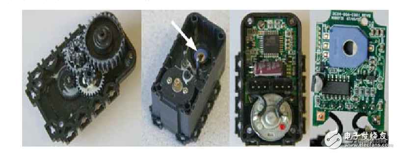
Figure 4.1 Internal structure and control diagram of the steering gear
When the AX-12 digital steering gear is used as a steering gear, the maximum angle of rotation is 300 degrees. It can be rotated freely when used as a motor. It has a wide range of applications. It is more convenient to control by digital signal control. Each servo has a unique ID number. Network drive mode, Daisy bus connection mode, can be connected in multiple mesh series, easy to connect. Its specific parameters are shown in Table 1.1.
Table 1.1 specific parameters of the steering gear
Project parameter project parameters
Weight 55g displacement angle 0-300° infinite rotation
Reduction ratio 1/254 minimum angle 0.35°
Working voltage 7VDC-12VDC communication half-duplex asynchronous serial communication
Operating temperature -5-85 degrees Celsius baud rate 7343bps-1Mbps
Maximum current 900mA command packet digital signal
Input voltage 7V10V physical connection TTL multi-channel (daisy bus)
Maximum torque 12 (Kgf?cm) 16.5 (Kgf?cm) material engineering plastics
Speed ​​0.269 (second / 60 °) 0.196 (second / 60 °) feedback position, temperature, load, voltage, etc.
Because the AX-12 is equipped with an ATmega8 microprocessor, it is used to receive the data packets sent by the controller. After the corresponding processing, the servo motor is sent a PWM signal to control the start and stop of the motor. Therefore, the control servo is actually to control the state and parameters of the ATmega8 servo are stored in the corresponding address of the RAM and EEPROM of the ATmega8. Controlling the servo is the process of reading and writing data to the corresponding address of the servo.
5AX-12 servo communication protocol
The AX-12 digital servo does not use PWM control like the general R/C servo motor (steering gear). Its control signal is digital signal. The main controller and servo are connected by TTL-Daisy bus, half-duplex asynchronous. Serial communication protocol ((8-bit data bit, 1-bit termination bit, no parity). The main controller controls the servo by sending and receiving data packets. There are two kinds of data packets: one is the instruction packet. This is the command sent from the main controller to the servo; the other is the status package, which is the servo return to the master. If the master sends an instruction packet to the servo with ID N, then only the ID The rudder opportunity feeds back the corresponding state and performs the required action. The control schematic is shown in Figure 5:

Figure 5 steering gear control schematic
6 Conclusion
In this paper, a wheeled mobile robot motion control system is designed: a mobile robot motion control system based on servo control. The system uses numerical control interpolation technology to track the trajectory and has the characteristics of high tracking accuracy. A DSP chip specifically designed for motor control was selected, which simplifies the design, improves the reliability of the module, and leaves enough room for future control algorithm upgrades. In this paper, the mathematical model of the trajectory estimation of the mobile robot planning path is different from the traditional one for the straight line and the arc, and the tracking path for the primary and secondary curves can be discretized. The motion control system adopts the master-slave control structure, that is, the host computer completes the complex calculation, transfers the processed data to the slave machine, and the slave machine completes the control of the trolley body, and conveniently realizes the stepper motor control. The motion controller executed by the slave has low cost, strong function and convenient use, and has a very broad application prospect.
Automotive Staple,Automotive Industrial Staple,Moistureproof Automotive Staple,Hog Ring Blunt Galvanized Nail
Zhejiang Best Nail Industrial Co., Ltd. , https://www.beststaple.com