1 Inner wheel difference principle
This article refers to the address: http://
The inner wheel difference is the difference between the turning radius of the front inner wheel and the turning radius of the rear inner wheel when the vehicle turns. Due to the existence of the inner wheel difference, the movement trajectories of the front and rear wheels do not coincide when the vehicle turns. The size of the inner wheel difference is related to the amplitude of the steering wheel and the length of the wheelbase of the vehicle. The greater the steering wheel rotation, the larger the steering angle, the larger the inner wheel difference, and the smaller the opposite; the longer the wheelbase of the vehicle, the more the inner wheel difference Large, otherwise the smaller. Heavy-duty car bodies are relatively long, especially after the car head turns over, there is a long body that has not turned around, and it is easy to form a “visual blind zone†for large-scale vehicle drivers. After passing through the inner wheel range, passers-by is prone to life-threatening danger. The shaded portion in Fig. 1 is the formation area of ​​the inner wheel difference.

Figure 1 Schematic diagram of internal wheel difference
2 Ultrasonic warning principle
2.1 Ultrasonic ranging principle
Acoustic waves with a resonant frequency higher than 20 kHz are called ultrasonic waves. Ultrasonic waves travel in a straight line. The higher the frequency, the weaker the diffraction ability and the stronger the reflection ability. There are various methods for ultrasonic ranging, such as phase detection, acoustic amplitude detection, and round-trip detection. Although the phase detection method has high precision, the detection range is limited; the acoustic amplitude detection method is susceptible to reflected waves. In this paper, the round-trip time detection method is adopted. The working principle is as follows: the ultrasonic transmitting probe emits an ultrasonic pulse to the medium, and the reflected wave must act on the receiving probe after the sound wave encounters the measured object. If the speed of sound in the medium is known to be V, the time difference between the moment of the transmitted pulse and the arrival time of the first reflected wave is T, then the distance between the probe and the measured object is S=VT/2, and the measurement of the change of the distance value can be achieved. Control purposes. The speed V of the ultrasonic wave is related to the temperature, and the relationship between the speed of sound in the air and the temperature can be expressed as:
 (1)
(1)
2.2 Arrangement of ultrasonic sensors in wheel differential detection
When the car is driving, it will turn to the left and turn to the right, so the ultrasonic sensor should be installed symmetrically on both sides of the body. In this system, a total of three pairs of sensors need to be installed, one pair is installed near the front wheel, in order to remind the driver whether the back of the body will hit the object inside the turn when turning; the second pair is installed near the middle of the wheelbase, in order to prevent objects in the car When turning, it suddenly appears on the inside of the turn; the third pair is installed in the rear wheel attachment, in order to promptly remind the driver of the dangerous situation.
3 system hardware design
The system combines single-chip technology, ultrasonic ranging technology and CAN bus communication technology to detect the inside condition of the car during the turning process. The three pairs of ranging sensors of the early warning system work independently, and the data is transmitted to the main controller via the CAN bus via the interface chip PCA82C250. The range is measured by SensComp 600 sensor and SensComp 6500 ultrasonic distance module; the main function of the low-cost AT89C51 is as follows: 1. It is used to control the distance measuring sensor and send the measured data to the CAN bus through the CAN controller SJA1000 in real time; The temperature parameter transmitted by the temperature sensor DS18B20 corrects the propagation speed of the ultrasonic wave in the air; the high-speed linear optocoupler 6N137 is also isolated between the PCA82C250 and SJA1000 to effectively prevent the transient interference of the car in the harsh working environment, ensuring The accuracy of data transmission. Because the hardware systems of the three pairs of ranging sensors are identical, only one is used for explanation. The hardware structure of the system is shown in Figure 2. 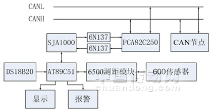
Figure 2 Hardware structure diagram of the wheel differential warning system
3.1 CAN bus communication module
The CAN bus protocol follows the ISO standard model and is divided into a data link layer and a physical layer. These two layers are usually implemented by CAN controllers and transceivers. CAN bus devices can be roughly divided into two types, one of which is with on-chip CAN controllers, such as 87C196CA/CB, MC6837, etc.; another CAN controller needs to be used independently with a microprocessor, such as Philips SJA1000, Intel Company 82526 and MCP251. The former is often used in many specific situations, and the integrated device is convenient for users to make printed boards, which makes the circuit design simplified, compact, and efficient; the latter is more flexible in use, and it can be used with various types of single-chip microcomputers and microcomputers. Make interface combinations. In this system, combined with the previously selected microcontroller, the SJAl000 of Philips Semiconductors was selected as the independent CAN controller. The main features of SJA1000: extended receive buffer (128 byte FIFO); support CAN 2.0B protocol; support 11-bit and 29-bit identifiers at the same time; bit communication rate is 1Mbits/s; enhanced CAN mode (PeliCAN); use 24MHz clock Frequency; support a variety of microprocessor interfaces; programmable CAN output drive configuration; operating temperature range of -40 ° C ~ +125 ° C, enough to adapt to a variety of harsh environments. The CAN bus driver uses the PCA820250 of Philips, which has high speed (up to 1Mbps), which can meet the requirements of real-time requirements such as self-braking. It has the ability to resist transient interference protection bus and reduce RF interference. Slope control. In addition, it can be connected to 110 nodes to prevent short circuits between the power supply and ground, and does not affect the bus when a node is powered down.
CAN bus communication module mainly consists of AT89C5l microcontroller, independent CAN communication controller SJAlO00 and CAN bus driver PCA82C250. In order to improve the anti-interference ability of the system, an optical isolator 6N137 is added between the SJAl000 and the CAN bus driver PCA82C250. When the microprocessor AT89C51 sends the ranging result data to the CAN bus controller SJAl000 through the P0 port, the parallel data is converted into serial data by SJAl000, which is sent from the port TX0, passes through the opto-isolator 6N137, and then reaches the CAN bus driver PCA82C250, and finally The data is sent to the CAN bus. Instead, data from the CAN bus can also arrive at the microprocessor through the corresponding circuitry. In this way, the communication function between the ultrasonic distance measuring sensor and the upper computer can be realized.
3.2 Introduction of ultrasonic sensors
This system uses single-chip AT89C51 to realize the control of SensComp 600 series ultrasonic sensor and SensComp 6500 ultrasonic ranging module. The SensComp 600 Series electrostatic transducers have a frequency of 50 kHz and a measurement range of 6 inches to 35 feet (0.15 meters to 10.7 meters). With the SensComp's 6500 drive circuit, the sensor can measure from 2.5 cm to 15.2 m. The AT89C51 controls the transmission of ultrasonic waves through the P1.0 pin, and then the microcontroller continuously detects the INT0 pin. When the level of the INT0 pin changes from low level to high level, the ultrasonic wave is considered to have returned. The data counted by the counter is the time elapsed by the ultrasonic wave. The distance between the sensor and the obstacle can be obtained by conversion. As shown in Fig. 3, the hardware schematic of the ultrasonic ranging is shown.
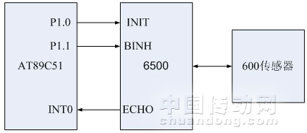
Figure 3 Schematic diagram of the hardware of the ultrasonic ranging circuit
3.3 Temperature compensation design
Since the temperature changes by 0.6 m/s for every 10 °C change in temperature, the effect of temperature on ranging is quite large. In order to achieve more accurate detection, this design uses the single-line temperature sensor DS18B20 from DALLAS Semiconductor. The sensor can directly read the measured temperature and can realize 9~12 digit digital value reading mode by simple programming according to actual requirements. The temperature range is -55°C~+125°C, the accuracy is ±0.5°C, and the field temperature is directly The digital transmission of “first-line bus†greatly improves the anti-interference of the system. The whole product is small in size, low in price and flexible in use, and can meet the requirements of the system in terms of temperature measurement accuracy, conversion time, transmission distance and resolution. . Figure 4 is a schematic diagram of the connection between the temperature sensor and the microcontroller.

Figure 4 Schematic diagram of the temperature correction part
4 system software design
The software adopts modular design, and the program consists of main program, ranging subroutine, CAN bus communication subroutine and other modules. During the debugging process, each function module and subroutine are debugged one by one. After each subroutine completes its specified function, it is integrated to complete the final comprehensive debugging. The main program flow chart and the ranging subroutine flow chart of the wheel difference warning system are shown in Figures 5 and 6, respectively. When the car turns to start the early warning system, the AT89C51 first sets P1.0 to 0, activates the ultrasonic sensor to transmit the ultrasonic wave, and starts the internal timer T0 to start timing. The ultrasonic sensor we use is integrated and transmitted. After the 16 pulses are sent, the ultrasonic sensor has aftershocks. In order to eliminate the transmission signal of the ultrasonic sensor from the return signal, the return signal must be detected after 2.38 ms after the start of the transmission signal. . When the ultrasonic signal hits the obstacle, the signal returns immediately, and the microprocessor continuously scans the INT0 pin. If the signal received by INT0 changes from low level to high level, it indicates that the signal has returned and the microprocessor enters the interrupt. Turn off the timer. Then, the data in the timer combined with the temperature sent by the temperature sensor is corrected and converted, and the true distance between the ultrasonic sensor and the obstacle can be obtained; then the distance measurement result is displayed, and if the distance measurement result is lower than the set threshold value, The alarm signal is generated; finally, the obtained distance data is transmitted to the automobile main controller through the CAN bus network in real time, so that the communication and network control functions of the early warning system and other nodes of the CAN network and the upper computer can be realized. 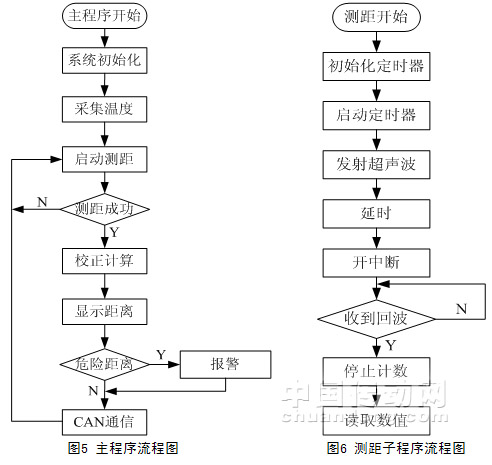
5 Conclusion
This paper proposes a wheel differential warning system applied to heavy-duty vehicles. Based on the principle of ultrasonic pulse ranging, the distance is measured, the data is corrected according to the site temperature, and the wheel differential warning system is connected with the digital platform of the car through the CAN bus. The influence of environmental factors has improved the detection accuracy of the system. The real-time display is based on the distance from the obstacle to the vehicle body. When the calculated distance is less than the safety distance, an early warning can be made to remind the driver to take necessary measures to avoid a collision accident. The system has simple structure and high reliability, and can economically and effectively reduce the incidence of wheel accidents of large vehicles, and has a good application prospect.
Corn Sheller,Hand Corn Sheller,Corn Sheller Machine,Hand Crank Corn Sheller
Hunan Furui Mechanical and Electrical Equipment Manufacturing Co., Ltd. , http://www.frcornthresher.com