With the continuous improvement of various science and technology, the automation technology continues to deepen, and the intelligent remote control technology will be applied across fields and will be widely popularized. The research of robotic car is part of the branch of mobile robot. It is a comprehensive system involving computer technology, sensing technology, communication technology and other related technologies. Its main function is to use wireless network video technology to realize the recognition path, control the speed and steering.
The car adopts STM32 MCU as the main controller, and realizes the transmission of remote video pictures through a Wifi RF module RT5350. The whole project covers a wide range of knowledge, including MCU programming technology, OpenWrt router system and Windows PC software development and other technical fields. . The following is divided into three levels to introduce the implementation of the video car:
(1) The underlying driver layer: the drive control of the car is realized by STM32 single chip microcomputer;
(2) Middle layer transport layer: transmission of control commands and video streams by means of the RT5350 router platform;
(3) Top-level control layer: Control the car on the Windows platform.
1, the underlying driver layerThe whole car is the movement of the STM32 single-chip microcomputer to control the movement of the trolley motor and the steering gear of the camera. Because the current provided by the STM32 MCU is very small, it is not enough for the car to move, so the motor drive module is needed. Here, the L298N module is used to drive the DC motor of the car.
1.1, motor drive principleThere are two motors on the left and right wheels of the car. The forward, reverse and stop of the left and right motor A and B determine the movement mode of the car. The STM32 MCU four motor control signal lines are connected to IN1~IN4 of L298N, and the other two PWM speed control signal lines are connected to ENA and ENB. The circuit diagram details are shown in Figure 1.
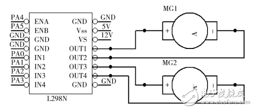
Figure 1 circuit schematic
Input signal lines IN1 and IN2 control the movement of motor A, and DC motor A is connected to OUT1 and OUT2. Similarly, IN3 and IN4 together control the motion of motor B. See Table 1 for details of the corresponding motion modes of the corresponding car.
Table 1 corresponding sports mode of the car
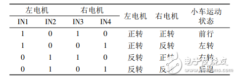
As shown in Figure 1 above, there are two signal input ports, ENA and ENB, on L298N. The function of these two ports is to enable the control signal and be active low. The L298N will follow the motion modes listed in Table 1 only when the signal line is pulled low.
Since the L298N has a control-enabled signal line, PWM regulation can be performed by controlling the signals of ENA and ENB. The principle is that the switch is turned on for a period of time T, and the average voltage across the motor is U=V*t/T=aV. Where a = t / T (duty cycle), V is the supply voltage. The rotation speed of the motor is proportional to the voltage across the motor, and the voltage across the motor is proportional to the duty cycle of the control waveform. Therefore, the rotational speed of the motor is proportional to the duty cycle of the PWM signal, and the duty cycle of the signal is larger. The sooner you get.
Product categories of Cloth Pen Nib, it is belong to Passive Stylus Pen. Passive stylus pen is characterized by being cheap and without charging. But compared with the active capacitive stylus pen, its tip diameter is larger, so it cannot be used in works with high precision. Using high-quality conductive cloth head, smooth contact with the screen.
Cloth Pen Nib,Multi-Functional Pen Stylus Pen,Stylus Pencil With Clip,Touch Stylus Pencil
Shenzhen Ruidian Technology CO., Ltd , https://www.szwisonen.com