LED lighting is becoming more and more popular in the automotive field, such as rear light groups (RCL), headlights, daytime running lights, signal lights and third headlights (CHMSL), and this trend is occurring in the original equipment manufacturing. Commercial and parts market lighting supplier field. In driving automotive LED lighting, there are many suitable switching power supply topologies available on the market, but the final choice depends on the LED's voltage and current requirements and must meet the overall system goals. For applications where the supply voltage is much higher than the load voltage, the buck converter is arguably the best choice because it provides a stable and continuous output current for the LED load. Conversely, if the total LED voltage is higher than the system's supply voltage, the system designer must use a boost/buck hybrid topology or a pure boost topology. However, in some cases, the LED's supply voltage can be higher, equal, or lower than the load voltage, and designers may need to use a SEPIC (single-ended primary inductor converter) topology. This article will cite National's LM3406 buck regulator and LM3421 controller as examples, and illustrate the advantages of individual topologies through different topologies, including buck, boost, buck/boost, and SEPIC. And shortcomings.
LED rear lamp group arranged in series and parallel
One of the more common applications of LEDs in automobiles is the taillight/flash combination, also known as the rear lamp cluster. For LEDs with a typical forward voltage (VF) of 3V, a step-down switching regulator may be required as a solution when the DC voltage flowing through them is 12-14 Vdc. At a minimum voltage of 12V, only three LEDs can be connected in series. If the total voltage of all LEDs exceeds 12V, a series/parallel connection is required (Figure 1).
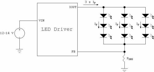
Figure 1. Simultaneous application of series/parallel arrangement.
For applications that require dimming and flashing, there are several ways to turn off the power to the LED string. One of the most common methods is pulse width modulation (PWM) dimming control, which is usually controlled by a dedicated signal. The output brightness of the light is not suitable for automotive applications because of the need to add a dedicated line to the line system for dimming purposes. Another way is the so-called two-wire dimming, in which the power supply to the LED driver is periodically interrupted to control the brightness and darkness. National's LM3406 is one of the devices built into this feature. Figure 2 shows the application circuit diagram of the LM3406.
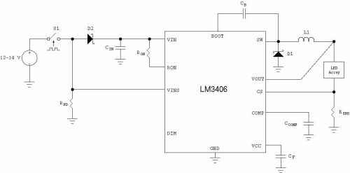
Figure 2. Two-wire dimming configuration for the LM3406.
This approach has three major advantages. First, the LM3406's input voltage sense pin (VINS) eliminates the use of dedicated dimming signals, allowing the PWM dimming of the LED string to be achieved by adjusting the power to the LM3406. Second, it is essential that the blocking diode D2 allows the circuit to retain the input capacitor CIN, as in the non-two-wire dimming solution, based on the buck regulator's discontinuity. The input current retains the output capacitor. Third, this configuration allows the device itself to remain driven without having to completely restart after the dimming cycle is complete. Additional components required for this standard PWM dimming method include the blocking diode D2, the VINS pull-down resistor RPD, and the parts required to disconnect the switch S1.