The core of this almost power-hungry remote doorbell is a new type of green storage component, a supercapacitor, designed with DC/DC conversion technology.
By using micro-power wireless transmitting and receiving modules and super capacitors to store electricity, the existing remote doorbell problems are completely solved. The DC/DC converter is used to solve the problem that the voltage of both ends of the super capacitor decreases continuously during the discharge process; the coding and decoding techniques are used to solve the electromagnetic interference and the mutual influence of the door and the door between the neighbors.
Figure 1 is the transmitting circuit. In addition to the button AN, there are only three electronic components, namely the micro-power transmitting module F05P, the encoding integrated circuit HX2262, and the resistor R. The usual transmitting circuit does not consume power. After pressing the doorbell normally open button AN, the encoding The data signal encoded by the integrated circuit HX2262 is sent to the micro power transmission module F050P, and then transmitted to the air. During the signal transmission, the operating current is also small. The measured total current is only 6 mA under the action of a 6V battery. The battery voltage used can be selected between 3 and 12V.
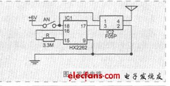
Figure 1 Transmitting circuit
Figure 2 is a receiving circuit. The core components are super capacitor C2, DC/DC converter BL8530, micro power remote control receiver module J04V, decoding integrated circuit HX2272 and music integration block TR95. AC mains capacity 0.033μF step-down capacitor C1, low power After the current limiting resistor R2, the bridge rectifier diode D1~D4, the Zener diode DW, and the LED, the super capacitor C2 is charged. The current is very small and only two mA. The electric energy stored in the super capacitor is converted by the BL8530 integrated circuit, the inductor L, the Schottky diode D5 and the capacitor C3, and the stable 3V DC power is supplied to the micro power remote control receiving module J04V, the decoding integrated circuit HX2272 and the music integrated circuit. When the transmitting circuit emits an electromagnetic wave signal, the receiving module J042 can receive the signal and send it to the input (14) pin of the decoder through the 2 pin. The decoder's (17) pin has a high level output only if the decoding settings in the decoder match the encoding settings in the encoder. The high level is applied to the trigger end of the music integrated block via the resistor R4, the capacitor C4, and the music selection switch K2, and the speaker emits a corresponding music sound. When the doorbell emits music, the current required for a few tens of milliamps is provided by the supercapacitor C2. Because the BL8530 can convert the voltage as low as 0.8V into a stable 3V output, the 2F super capacitor can ensure that the doorbell continues to sound for more than 20 seconds after calculation and actual use, which is equivalent to pressing the doorbell ten times to meet the general household use. . The supercapacitor charges back to about 3V after more than 20 seconds of continuous sounding, as long as ten minutes. When not in use, you can unplug the entire doorbell from the AC outlet and disconnect the power switch K1.

Figure 2 Receive circuit
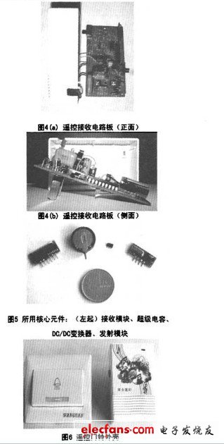
The transmitting part of the circuit board is shown in Figure 3, and the receiving part of the circuit board is shown in Figure 4. The core components used are shown in Figure 5. The housing is shown in Figure 6.

Figure 3 remote control transmitter circuit
Gas Generator Set,Coal Gas Power Generator Set,Oil Field Gas Generator,Methane Gas Generator
Jiangsu Vantek Power Machinery Co., Ltd , https://www.vantekgenerator.com