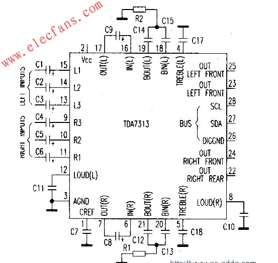
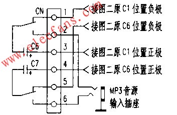
The car's audio system has only two functions: radio and tape player. Can you use the existing audio system to play MP3 music? The author has studied this car audio circuit and found that its function adjustment is controlled by the bus. The model of the signal selection IC is TDA7313, as shown in the middle diagram. The left channel signal is switched through the pins (13), (14) and (15), and the right channel is switched through the integrated circuits through the pins (9), (10) and (11). The radio signal is input through pins (11) and (15), and the tape player is input through pins (10) and (14). Although the two remaining inputs are not used. But the circuit is controlled by the bus, and it is impossible to modify the software. Only find ways to change the hardware. After analysis. It is easier to modify the radio. First, solder down Cl and C6 in the middle picture to the position of C6 and C7 in the above picture. Pins (1) and (5) of the signal terminal CN are connected to the negative poles of the original C1 and C2 positions in the middle picture with shielded wires, and pins (3) and (4) are respectively connected to the positive poles of the original positions C1 and C2 in the middle picture On the (2) pin and (6) pin plus a signal input socket, as MP3 sound source input. The signal input socket and the signal switching key AN are respectively installed at appropriate positions on the audio control panel. The + KV power supply in the figure above is connected to the (2) pin of TDA7313 with a lead, and + 12V is connected to the input power of the audio system. The modified circuit is shown in the figure below. In order to ensure that the audio signal is not distorted, a small relay is used to switch the signal. After the author's design and continuous improvement, the circuit shown in the figure is finally formed.
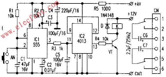
The switch circuit is composed of two integrated circuits, ICl (NE555) and IC2 (CD4013). ICl and peripheral components form a monostable trigger, and IC2 and peripheral components form a bistable circuit. The control principle is introduced as follows: When the power of the audio system is turned on, the + KV terminal inputs 5V power, and the voltage across C1 cannot be abrupt. ICl outputs high level.
Turn IC2 over, VT turns on, the relay pulls in, and the signal is switched to the signal input socket, which is not allowed by us. So just connect R2 and IC3 to the (4) pin of ICl to form a power-on reset circuit. Make the reset time Tl greater than the charging time TO of Cl. In addition, connect a capacitor to the negative pole of IC2 (11), so as to ensure the accuracy of the control, or change the previous state when starting up. Use MP3 as the audio source input. After inserting the MP3, press the touch button once. AN, ICl (2) pin voltage is 0, less than 1 / 3VCC, (3) pin output high level, IC2 flip output high level, VT is turned on, relay K pulls in, contact switch to signal input socket Now you can enjoy MP3 music. After releasing the key AN, the power source charges Cl through R1. When the voltage is higher than 2 / 3Vcc, it outputs a low level and waits for the next key press. When we want to listen to the radio, we just need to press AN again, ICl outputs high level again, IC2 flips and outputs low level again. The relay K is de-energized, the normally closed contact is closed, and the radio signal channel is connected.
Big Water Tank Robot Vacuum Cleaners
Big Water Tank Robot Vacuum Cleaners,Ultrasonic Cleaner Water Tank,Robot Vacuum Cleaner,Virtual Blocker
NingBo CaiNiao Intelligent Technology Co., LTD , https://www.intelligentnewbot.com