The large-scale use of traditional transformer rectifiers and non-linear loads makes the current harmonic content in the power grid higher, which has a great impact on the aircraft power supply system and power supply quality. Eliminating harmonic pollution of the power grid and improving the power factor of the rectifier are hot topics in the field of power electronics research. Space vector PWM (SVPWM) control has the characteristics of high DC side voltage utilization rate, fast dynamic response and easy digital realization. This paper uses space vector technology to study the three-phase voltage-type rectifier to make the grid side voltage and current in phase, so as to achieve high power factor rectification.
1 Space vector control technology
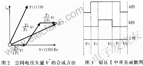
The SVPWM control technology controls the combination of different switch states to control the space voltage vector V to rotate circularly according to the set parameters. For any given space voltage vector V can be synthesized from these eight space vectors, as shown in Figure 1. The voltage vector V of any sector area can be obtained by different combinations of two adjacent non-zero vectors and zero vectors in this area in time. The action time of these vectors can be applied at once, or can be applied multiple times within a sampling period. That is to say, by controlling the action time of each basic space voltage vector, SVPWM finally forms a PWM pulse wave of equal amplitude and unequal width, so that the voltage space vector rotates close to a circular locus. The higher the switching frequency of the main circuit power switch tube, the closer to the circular rotating magnetic field.
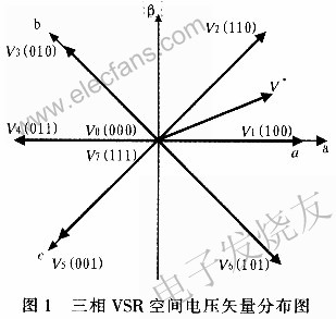
In order to reduce switching times and switching losses, for a given space voltage vector of three-phase VSR
2 Direct current control strategy
The current control strategy of three-phase VSR is mainly divided into direct current control and indirect current control. Direct current control uses grid-side current closed-loop control, which improves the dynamic and static performance of the grid-side current and enhances the robustness of the current control system. In the direct control strategy, the fixed switching frequency PWM current control is better applied because of its simple algorithm and more convenient implementation. In the three-phase static coordinate system, the fixed switching frequency PWM current controls the steady-state current of the inner loop The command is a sine wave signal, the amplitude signal of the current command comes from the output of the DC voltage regulator, and the frequency and phase signals come from the power grid; the PI current regulator cannot realize the current without static difference control, and the active current and reactive power Independent control of current is difficult to achieve. The current command in the two-phase synchronous rotating coordinate system (d, q) is a constant signal when DC, and its PI current regulator realizes the current without static error control, which is also conducive to separate active current
3 Three-phase VSR digital control system
The structure of the three-phase VSR digital control system is shown in Figure 4. The control system uses a voltage outer loop and two current inner loops to form a double-loop control structure. The voltage loop controls the three-phase VSR DC side voltage, and the output DC side voltage Vdc and the given reference Voltage

Three-phase PWM rectifier adopts the idea of ​​motor vector control to regulate voltage by controlling current. The three-phase current after sampling is transformed by CLARK and PARK coordinates to obtain the id and iq components in the two-phase rotating coordinate system. The voltage error signal is adjusted by PI as the active current command value, while the reactive current
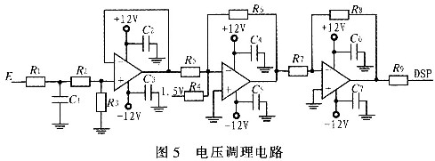
3.1 AC side voltage conditioning circuit
The given input voltage on the grid side of the system is 115 V three-phase AC. When the voltage is sampled, the transformer is used to step down the sample, and then the voltage signal is adjusted to make the voltage signal value between 0 and 3 V required by the data acquisition terminal of TMS320F281 2. , Voltage conditioning circuit shown in Figure 5.
3.2 DC voltage conditioning circuit
The output voltage on the DC side is about 350 V. To achieve data collection on the DC side voltage, an operational amplifier is used to form a two-input amplifier circuit. The output voltage on the DC side is converted to within the range of O ~ 3 V by selecting a reasonable parameter value. Send to the AD interface of the DSP.
3.3 TMS320F2812 program initialization process
Through detailed analysis of the space vector pulse width modulation technology control algorithm and the modeling and simulation of three-phase VSR, it is found that the SVPWM control algorithm has the characteristics of being convenient for digital realization. The fixed-point TMS320F2812, which has been developed and has developed relatively low power consumption, low cost and considerable integration, is selected as the core controller. The device is a new generation of low-cost, high-performance 32-bit fixed-point digital signal processor DSP launched by Tl. The digital signal processor is an important part of the three-phase high power factor rectifier. The software part realized by TMS320F2812 mainly includes main program and interrupt subroutine. The main program is mainly to complete the initialization work of the system, including the system clock setting, the value of the initialization register and the global interrupt and the event manager interrupt to enter the working state. The program flow is shown in Figure 6.

4 Test results
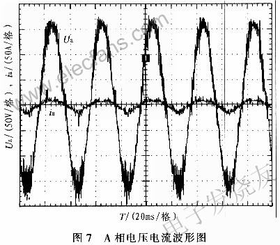
According to the mathematical model and related principles of the three-phase VSR, an experimental circuit was built and tested in the laboratory. In the test, the power supply is a 115 V / 400 Hz three-phase AC power supply. When the load is 217 Ω, the waveforms of the phase A input voltage and phase A input current on the grid side are measured as shown in FIG. 7, from which the input voltage and The input currents are in phase, thus achieving high power factor rectification.
5 Conclusion
In order to meet the requirements of aviation rectifiers for low harmonics, high power factor, fast response, and DC output stability of the rectified power supply, a new SVPWM control strategy that is convenient for digital implementation is proposed by using input voltage space vector orientation. It can be seen from the test results that the grid-side current of the rectifier designed by the space vector control technology follows the grid-side voltage well, realizing high power factor rectification and meeting the design requirements.
Film Temperature Measurement Thermistor
Film temperature measurement NTC Thermistor is small and light as to be convenient to mounting. With the characteristics of high stability and reliability, superior electrical insulation and fast response, this type of thermistor can be used in household appliance, computer and printer etc.
Film Temperature Measurement Thermistor
Film Temperature Measurement Thermistor,Computer Sensors,Cpu Thermometer,Cpu Temp Monitor
Feyvan Electronics Technology Co., Ltd. , http://www.fv-cable-assembly.com