This paper introduces a car anti-collision and anti-theft alarm system that combines the real-time control and data processing functions of the single-chip microcomputer with the ultrasonic ranging technology and infrared sensor control technology.
Keywords: single chip microcomputer; anti-theft anti-collision; alarm
This article refers to the address: http://
Huaian 223001, China)

(2) Display mode: static continuous display;
(3) Detecting the human body: using infrared sensors, if there is a theft, the signal can be transmitted to the single-chip microcomputer in time;
(4) Alarm processing: over-limit judgment of the measured parameters, such as over-limit, giving an audible and visual alarm;
(5) Transmitting and receiving functions: realized by the anti-theft transmitter and receiver, controlled by the single-chip microcomputer; and the remote controller remotely controls the anti-theft signal.
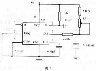
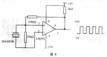
1.4 Working principle (1) Selection of sensor The anti-collision system of the vehicle involves the detection of the distance. According to the measurement environment and requirements, the ultrasonic ranging has the characteristics of high measurement sensitivity, strong penetrating power, fast measuring speed and large measuring angle. It can detect objects in a wide range. This system uses MA40EIS ultrasonic emission sensor and MA40EIR receiving sensor.
The anti-theft system uses infrared sensor TX05D, which is an "integrated" infrared transmitting and receiving device. It contains infrared transmitting, receiving, signal amplifying and processing circuits. It can detect human body or object in a certain range in front without contact. And converted to a high level output. The TX05D uses low-power devices and anti-interference circuits internally for stable, reliable operation and excellent performance. 
(2) Anti-collision detection This system selects the single-chip AT89C51 as the signal controller. The specific working process is as follows: the anti-collision switch is connected to the P2.1 pin of the AT89C51. When the switch is closed, the P1.5 end of the AT89C51 is set to 0 to transmit ultrasonic waves, and the counter starts counting. The ultrasonic receiving circuit receives the signal and inputs the signal to the interrupt 1 (triggered by the edge). When the signal is received, the counter is turned off, the count value is read, and the distance is calculated; the distance is compared with the alarm distance, and when the distance is smaller than the alarm distance, the display distance is displayed. And AT89C51 P1.6 is set to 0 for sound and light alarm, when it is greater than the alarm distance, no alarm.
(3) Anti-theft detection
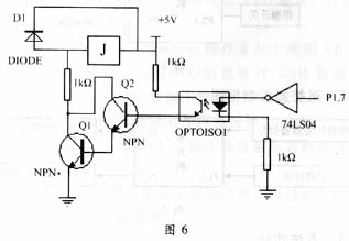
The infrared sensor integrated circuit inputs a valid signal to the AT89C51 microcontroller. When the infrared sensor detects the human body, the output high level is received by the single-chip microcomputer through the inverter to perform anti-theft control, and the control transmitter sends an anti-theft signal (pulse), and the driver receives the signal through the remote controller nearby, and performs corresponding disposal. Turn off the startup circuit.
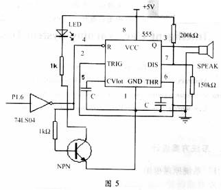
The specific working process is as follows: The anti-theft switch is connected with the P2.0 pin of the single-chip microcomputer. When the switch is closed, it enters the anti-theft state and delays for a period of time to ensure that the owner leaves and prevents false alarms. When the TX05D detects the human body, it outputs a high level via the inverter, and then sets the P1.6 end of the MCU to 0 for sound and light alarm. The P1.7 terminal is set to 0 to cut off the startup circuit. At this time, the P1.4 terminal emits a continuous 50 kHz. After the pulse is buffered, it is transmitted by the transmitter CZ-7F, and is received by the remote controller for sound and light alarm.
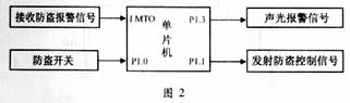
The working process of the remote control is as follows (Fig. 2): The remote control has built-in single-chip AT89C51. When the interrupt 0 receives the edge trigger signal, it enters the alarm program, and the P1.3 end of the single-chip microcomputer sets 0 to perform the sound and light alarm. When it is detected that the close switch is closed, the sound and light alarm is turned off; the P1.1 output pulse signal of the single chip microcomputer, the transmitter transmits the frequency signal, and is received by the alarm device in the car (this control is to prevent the sound and light alarm in the car from false alarm) At the same time, the remote control's own interrupt 0 is turned off to prevent false alarms. 
 
 
2.3 anti-theft transmitting circuit and receiving circuit (1) transmitting component CZ-7F: internal high-frequency tube MPSH10 for carrier oscillation and transmission, plus one input signal transistor 8050 amplifier and so on. The modulation method is frequency modulation, the carrier frequency is 280MHz, the working voltage is 6~12V, and the modulation voltage is 6V. The component has three pins, the 1-pin UDD is the positive power supply terminal, the 2-pin is the modulation signal input terminal, and the 3-pin USS is the negative power supply terminal.
(2) Receiving component CZ-7J: It consists of a detection demodulation circuit and a power circuit LM358, and is used in combination with the CZ-7F. The operating voltage is typically 6V. There are also three external pins: 1 pin UDD is the positive power supply terminal, 2 pin is the demodulation signal output terminal, and 3 pin USS is the negative power supply terminal. The remote control module has mature circuit, stable operation and high reliability. It can be used to transmit digital signals or analog signals with an effective working distance of not less than 600 meters. All components including the antenna have been adjusted.
(3) Anti-theft transmission circuit: The P1.4 end of AT89C51 is high level during normal operation, no pulse is transmitted, and the transmitter does not work. When an anti-theft signal is detected (ie, when the human body is in use), the internal program uses a timer to control the transmission of a 50 kHz pulse, which is buffered by the inverter, and the transmitter operates to emit the desired signal.
(4) Anti-theft receiving circuit: When the transmitter on the remote controller transmits a pulse, the receiver receives the signal, and the signal output after the amplification and shaping is received by the MCU interrupt port, and is transferred to the corresponding interrupt program for processing.
3.2 Software function (1) Monitoring function: When the monitoring button is pressed, the MCU makes corresponding processing;
(2) Display function: display distance and alarm information;
(3) Interrupt function;
(4) Data conversion function. Due to space limitations, the main program flow chart is omitted.
LED street lamp refers to the street lamp made with LED light source, which has the unique advantages of high efficiency, safety, energy saving, environmental protection, long life, fast response speed, high color rendering index, and is of great significance to urban lighting energy saving.
Led Road Light,Led Off Road Lights,Led Roadway Lighting,Cob Led Road Light
Yangzhou Heli Photoelectric Co., Ltd. , http://www.heli-eee.com