The ultrasonic sensor technology used in the parking obstacle detection system can detect nearby obstacles and provide the driver with a reverse warning and auxiliary parking function. The principle is to use ultrasonic waves to detect any obstacles present on or near the reverse path and issue them in time. caveat. The designed detection system can provide both audible and visual audible and visual warnings with warnings indicating the distance and direction of obstacles detected in the blind spot. In this way, in a narrow place, whether parking or driving, with the reverse obstacle alarm detection system, the driver's psychological pressure will be reduced, and the necessary action can be taken with ease. The PIC l8F8490 microcontroller and ultrasonic sensor are cheap and can be used on many models.
This article refers to the address: http://
Then what is the reverse sensor detection system based on ultrasonic sensors? To understand this, you should first understand the technical problems of ultrasonic sensors.
Ultrasonic sensor system configuration and working program (see Figure 1)
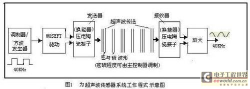
It consists of a transmitting sensor (or ultrasonic transmitter), a receiving sensor (or ultrasonic receiver), a control part and a Power Supply part. The transmitter sensor consists of a transmitter and a ceramic vibrator transducer with a diameter of about 15 mm. The transducer functions to convert the electrical vibration energy of the ceramic vibrator into ultrasonic energy and radiate into the air; and the receiving sensor is transposed by a ceramic vibrator. The device is composed of an amplifying circuit, and the transducer receives the ultrasonic wave to generate mechanical vibration, converts it into electric energy, and uses it as an output of the sensor receiver to detect the transmitted ultrasonic wave. In actual use, the ceramic vibrator that transmits the sensor is also used. It can be used as the ceramic vibrator of the receiver sensor. The control part mainly controls the pulse chain frequency, duty cycle and sparse modulation and counting and detection distance sent by the transmitter. The power source (or signal source) of the ultrasonic sensor can be DC12V. ±10% or 24V±10%.
When a high-frequency voltage of 40 kHz is applied to a piezoelectric ceramic piece (double crystal oscillator) having a resonant frequency of 40 kHz in the transmitting sensor, the piezoelectric ceramic piece is elongated and shortened according to the polarity of the applied high-frequency voltage, and thus an ultrasonic wave of 40 KHz frequency is transmitted. The ultrasonic wave propagates in a dense form (the degree of density can be modulated by the control circuit), and the ultrasonic waveform is shown in Figure 1 and transmitted to the ultrasonic receiver. The receiver uses the principle of piezoelectric effect, that is, on the piezoelectric element. Applying pressure to strain the piezoelectric element produces a 40KHz sinusoidal voltage with one side being a "+" pole and a "-" pole on the other side. Since the high frequency voltage has a small amplitude, it must be amplified.
According to the equivalent circuit and impedance characteristics of the ultrasonic sensor, it is known that the transmission sensor operates in series resonance, that is, the impedance Zr is the lowest at the resonance frequency fr, so that the maximum power can be supplied, and a large vibration sensor can be used; It works in parallel resonance, that is, the impedance Zα is the highest at the resonance frequency fα, and it is difficult to supply high power, but the impedance Zα is high to obtain a large amplitude signal, so the sensitivity of fα is used as a sensor.
The reverse operation of the ultrasonic transducer works in a reflective manner, that is, the transmitting sensor transducer transmits an ultrasonic wave of 40 KHz frequency, and after the obstacle is reached, the reflection is received by the transducer of the receiving sensor and converted into an electrical signal, see Figure 2 shows.
Its propagation medium is air.

Design scheme of reversing obstacle detection system based on ultrasonic micro-controller technology#e# Design scheme of reversing obstacle detection system based on ultrasonic micro-controller technology
Figure 3 is a block diagram of the design scheme of the vehicle reversing obstacle detection system.
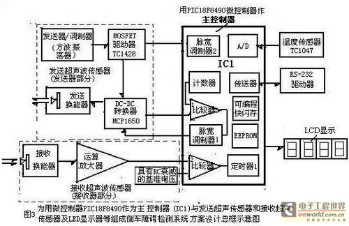
The design includes: IC1 master - for the use of Microchip's PIC l8F8490 microcontroller as the master of the car's reverse obstacle detection system; the transmitting part (ie sending the ultrasonic sensor) and the receiving part (ie receiving the ultrasonic sensor); temperature Sensor (TC1047A), communication interface RS-232 driver and peripheral circuits such as LCD or LED display.
Using a microcontroller as the master of the detection system
The microcontroller is the heart of the reversing detection system. Microchip's PIC l8F8490 microcontroller is ideal for applications such as automotive body control. Because it is a flash memory, power management microcontroller with on-chip LCD driver control module, running at 10MIPS-10 million instructions per second (MIPS), 16KB flash memory, 768 bytes of RAM, with an LCD controller Two PWMs, two comparators and four timers are shown in Figure 3, intermediate IC1. It is therefore the master of a highly integrated solution for reversing ultrasonic sensor applications. The microcontroller uses nanoWatt technology to implement power management functions that significantly improve power efficiency and system reliability, and meets low power design requirements including driving LCD displays in sleep mode. Its family of products offers up to 192-segment LCD drivers for a wide range of embedded control applications in a variety of package sizes and integration features.
Transmitter part control
The transmitter transmits a 40KHz pulsed square wave at a rate of 4-5 times per second during 1mS. To generate a transmit pulse chain, a driver can be used to drive the ultrasonic transducer. The driver is Microchip's TCl428 MOSFET driver. Shown on the left. Because the standard frequency of the actual ultrasonic sensor characteristics is 40KHz, the 40KHz pulse square wave chain sent by the transmitter is a universal transmission frequency, but the ultrasonic frequency is not fixed. It can be selected according to the blind zone range and the obstacle distance. The standard frequency (or The higher the center frequency, the shorter the distance measurement, and the higher the resolution, the standard frequency of common super wave sensors is 30KHz, 4KHz, 75KHz, etc.
Timer 1 begins counting when the transmitter sends the rising edge of the first pulse. Since the voltage amplitude of the required pulse chain is higher than the system voltage (+5V) (this is determined by the desired source of the transducer), this The transmitter section should contain a boost circuit. Here's a simple way to boost the voltage effectively, using Microchip's MCPl650 step-up DC/DC controller, which requires only one capacitor, one inductor, and two resistors to easily select the desired output voltage. The function of PWM1 (pulse width modulator) in the main controller IC1 is to adjust the output voltage of the booster circuit to a constant value.
Receiver section control
The receiver section includes an ultrasonic receive transducer, amplifier, filter, and a comparator as shown in the lower left side of Figure 3. The output of the receiving transducer is a low amplitude sine wave with the same frequency as the transmitted pulse train. In order to amplify the signal output from the transducer, Microchip's MCP6293 operational amplifier can be used. The feature of this op amp is that it has a 10MHz bandwidth and a pin-selectable low-power mode, although the package is small. The output signal can be transmitted to an LC bandpass filter circuit (also known as an amplitude detection circuit). The center frequency (standard frequency) of the bandpass filter is the same as the standard frequency of the receiver of 40 KHz. The function of the amplitude detection circuit is to receive The pulse is converted to a smooth, complete waveform whose high frequency noise is filtered out so that a detected signal is formed. This signal is then passed to the comparator for comparison with the attenuated voltage. It should be noted that the comparator's reference voltage is an attenuated voltage (generated by the RC RC circuit) so that the attenuation reference is attenuated over time. The signal. Until the time is less than a preset distance value, the timer 1 stops counting.
Ultrasonic sensor selection and parameters
Domestic TC40-167R series or MA40S2S (transmitting sensor), MA40S2R (receiving sensor) ultrasonic sensor can be used. The main parameters are (taking TC40-167R as an example): standard frequency 40±0.1KHz; sensitivity (dB) ≥-68; Sound pressure (dB) ≥ 114; direction angle (degrees) 60; electrostatic capacity / pf-2500; operating temperature (°C) - 20 ° C - + 70 ° C; effective distance ≥ 15M, effective distance of reflection receiving is 4M-7M.
About the detection distance display of the reverse obstacle
The detection system warns the driver when an obstacle is detected, and the new vehicle reverse obstacle detection system can use multiple sets of transmitting and receiving ultrasonic sensors to expand the detection range according to the actual use environment, thereby improving the accuracy of obstacles. The nearest obstacle is detected and displayed, so the LCD or LED display of the reverse obstacle detection system displays the number of the nearest obstacle.
Method for calculating ultrasonic distance
Ultrasonic waves are sent out in the form of a pulse train, which is the center frequency (or standard frequency). Timer 1 of the PIC l8F8490 master (shown in IC1 of Figure 3) counts from the rising edge of the first pulse until the master receives a decaying received signal that is less than the set value (ie, when Timer 1 stops counting when the distance is less than a preset value. Therefore, the measured time interval (the time difference between the transmitted signal and the received reflected signal) Δt multiplied by the speed of sound is equal to twice the measured distance L (2ΔL). If the propagation speed of the ultrasonic wave at the temperature T is V, the microcontroller can calculate the distance between the vehicle and the obstacle. The formula for calculating the measured distance is:
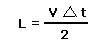
For this reason, as long as the distance is less than a predetermined value, not only the display but also an audible and visual alarm signal will be issued.
Solve the problem of improving the performance and accuracy of the reversing detection system
Transducer selection and installation
There are several different implementation options to choose from depending on the accuracy, distance and system cost required. The greater the frequency and power of the transducer, the higher the accuracy. The higher the transducer frequency, the smaller the volume, making the system easier to install in the car. A low frequency transducer is also advantageous, with a larger detection range and easier detection of objects around the transducer. An inexpensive technique to reduce interference is to add a 3 cm tube around the receiving transducer so that it can receive an effective signal and increase directivity.
An important factor affecting system performance degradation is crosstalk between the transmitter and the speaker. Only the effect of the transmitted pulse in the receiving transducer disappears and the received signal can be detected. It is important to minimize mechanical coupling between these two components. The technique that can be employed is to mount each transducer on a different PCB. If they share a substrate, a thin piece of foam can be placed behind the transducer. If the transmit-receive uses a single-transducer solution, then a sufficiently long delay should be set by the software after the transmission and before the receive portion is enabled. Any protective coating should be avoided for the transducer. All of these techniques improve the performance of ultrasound systems.
About the improvement of system accuracy, the temperature sensor eliminates this error.
Since the propagation speed of the ultrasonic wave changes as the ambient temperature changes, this will cause a ranging error. The temperature sensor TCl047A is used to measure the air temperature and then sent to the A/D converter in the main controller for temperature compensation, which can eliminate the error.
Improve receiver LC bandpass filter performance to increase signal fidelity and system accuracy. The extra gain level of the reflected signal also helps to increase the detection range and improve accuracy.
Conclusion
The above-mentioned design scheme of the vehicle reversing obstacle detection system is a combination of a microcontroller and an ultrasonic sensor, and is a solution for improving driving safety and experience. As the system can identify obstacles in the driving blind zone, the driver will be more comfortable to drive.
Through comparison of the schemes, the micro-controller-based reverse obstacle detection system is much more convenient and flexible than simply using a hardware circuit system (such as a LM1812 chip with built-in transmission and reception circuits and a peripheral circuit). Taking advantage of software technology, it can not only increase the function according to the operation and parking environment, but also replace many hardware circuits, making the parking obstacle detection system more reliable and accurate.
SMT Pulley , original and new, in stock, low cost, quality guarantee.
XA Pulley bracket L ASSEMBLY
XA Pulley bracket R ASSEMBLY
YA Pulley bracket L ASSEMBLY
YA Pulley bracket R ASSEMBLY
Smt Fuji Pulley
Original Smt Pulley
Smt Pulley
Smt Conveyor Belt Pulley
Smt Motors
Smt Juki Motors
Original Smt Servo Motor
Original Smt Motors
Holder For Smt Type
Smt Battery Holder
SMT Holder
Battery Holder
Filter For Smt Machine
High Quality Smt Filter
Smt Filter
Smt Machine Filter
Smt Tape Feeder Parts
Smt Machine Spare Parts
Original Smt Feeder
Original Smt Cable
Smt Machine Cable
Smt Spare Parts Fuji Cable
SMT Cable
SMT Belt
Smt Siemens Belt
Smt Juki Belt
Smt Conveyor Belt
Smt Camera
Smt Laser
Camera For Smt
Smt Siemens Camera
Smt Parts Plastic Rail
SMT Plastic Rail
Smt Juki Plastic Rail
Juki Plastic Rail
Smt Nozzle For Yamaha
Yamaha Nozzle
Nozzles For Yamaha Machine
Smt Yamaha Nozzle
Smt Siemens Nozzle
Smt Nozzle For Siemens
SIEMENS Nozzle
Smt Nozzle For Samsung
SAMSUNG Nozzle
Smt Samsung Nozzle
Panasonic Nozzle
Smt Panasonic Nozzle
Smt Nozzle For Panasonics
Smt Juki Nozzle
Nozzles For Juki Machine
JUKI Nozzle


SMT Pulley
Original Smt Pulley,Smt Pulley,Smt Fuji Pulley,Smt Conveyor Belt Pulley
Shenzhen Srisung Technology Co.,Limited , http://www.sr-smt.com