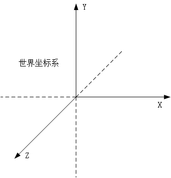
The OPENGL coordinate system can be divided into: world coordinate system and current drawing coordinate system.
World Coordinate System: In OpenGL, the world coordinate system is based on the center of the screen (0, 0, 0) and is always constant. You face the screen. Your right side is the x axis, the top is the y axis, and the screen points to your z axis. The unit of length is determined by this: The window range is exactly (-1,-1) to (1,1) in this unit, ie, the coordinate in the lower left corner of the screen is (-1,-1), and the coordinate in the upper right corner is (1,1) .
Current drawing coordinate system: It is the coordinate system when drawing the object. When the program was just initialized, the world coordinate system and the current drawing coordinate system are coincident. After translating, scaling, and rotating the current drawing coordinate system with glTranslatef(), glScalef(), glRotatef(), etc., the world coordinate system and the current drawing coordinate system no longer coincide. Note that the translation rotation here is a rotation translation of the current drawing coordinate system as a whole in the world coordinate system. Then, after the change, when drawing with the drawing function such as glVertex3f(), all the drawing coordinates are drawn in the current drawing coordinate system, and all the function parameters are also relative to the current drawing coordinate system.
Homogeneous coordinatesJust talking about three-dimensional situation
In vector space, only scalars and vectors
Vector + Vector = Vector
Scalar * Vector = Vector
In a three-dimensional vector space, it can be regarded as an arbitrary set of linearly independent vectors
Base V = [v1, v2, v3]
Other vectors can be represented by a three-dimensional tuple
Vector a = [A1, A2, A3]
Then the vector a = A1 * v2 + A2 * v2 + A3 * v3
Only vectors can't represent geometry, at least a bit
It is generally believed that the representation of a point is also a three-dimensional tuple
Point b = [B1, B2, B3]
This makes it impossible to distinguish between points and vectors.
Affine space
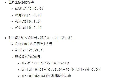
In the affine space, the base is called a frame and consists of three vectors and one point.
Frame V = [v1, v2, v3, p]
Affine space operation
Vector + Vector = Vector
Scalar * Vector = Vector
Point + Vector = Point
PS: As you can see, the sum of point and vector is another point. In fact, it can also be considered that the vector records the movement of a point and records the information of a point transitioning to another point.
then
Vector a = [a1, a2, a3, 0]
Point b = [b1, b2, b3, 1]
which is
a = a1 * v1 + a2 * v2 + a3 * v3 , indeed vector
b = b1 * v1 + b2 * v2 + b3 * v3 + p
b = vector + p = point
Reluctantly separated from Kazakhstan
There are problems
Point p and vector v1v2v3 how to determine? Their value is again in that frame or base?
Therefore, even more discussions have been held. In fact, this frame is still approaching our ordinary three-dimensional coordinate system.
Point p is the origin
V1 v2 v3 corresponds to three axes [1,0,0], [0,1,0], [0,0,1]
But I also tell you that for any point and any three linearly independent vectors v1 v2 v3, it can be used as a frame. Because three linearly independent vectors can represent any vector, and based on one point, it can represent any one point.
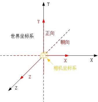
So think OpenGL default, its world coordinate system affine space, p is the origin, v1v2v3 as the axis
But the camera coordinate system is not, because? Because the camera can move, you can change the orientation and the forward direction, which affects the camera coordinate system. Just for mobile:
The default position of the camera is at the origin of the world coordinate system. After moving, it is not.
Then you look at the point on the world coordinate system in the position of the camera. The coordinate representation of those points should be converted to the camera coordinate system, which corresponds to the position of the point we really should see.
Or write and write coordinate systems
Coordinate SystemWorld coordinate system
World coordinate frame
Camera coordinate system
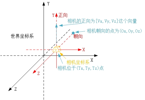
The default position of the camera is the origin of the world coordinate system. The orientation is the negative direction of the Z axis, and the positive direction is the positive direction of the Y axis.
Consider the camera
The location is the location of the camera, which is where to observe the world
Orientation is the direction the camera is pointing
The forward direction is how the camera should be placed after this position and the direction. For example, in general, we take pictures, vertical pictures are vertical pictures, horizontal pictures are horizontal pictures.
In fact, these parameters are also expressed in the world coordinate system.
The default camera coordinate system
After moving the camera, the camera's position, orientation, and positive direction change
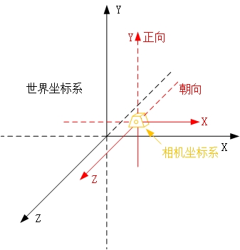
However, the vertex data is still in the world coordinate system, and we need to generate the image is dependent on the camera, so we have to convert the vertex to the camera coordinate system, this is the view conversion.
The vertex representation of the view conversion is relative to the camera coordinate system, but its frame is still logically the origin + three coordinate axes
Clipping coordinate system
This is only an external parameter of the camera, we also need to determine
The point in the three-dimensional area of ​​that piece will not be photographed until it is used to generate the image. That is, I need to define a "visual scene" to determine the scope of the photo.
Do you need perspective effects, etc.
Or coordinate transformation is more realistic
Coordinate transformationOpenGL mainly has two matrices, model view matrix and projection matrix
Model view matrix
Changes to the vertices in the world coordinate system, such as translation, rotation, and scale (model) are all changes to the vertices, and the camera's position, orientation, and positive changes (views) also need vertices from the world coordinate system. Converted to relative to the camera coordinate system, although these two are different changes, but are all operations on the vertices, so you can use a matrix to record
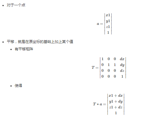
That is, as long as the left shift matrix is ​​based on the original point, the coordinates of the point can be translated.
The translation matrix T is recorded as T(dx,dy,dz).
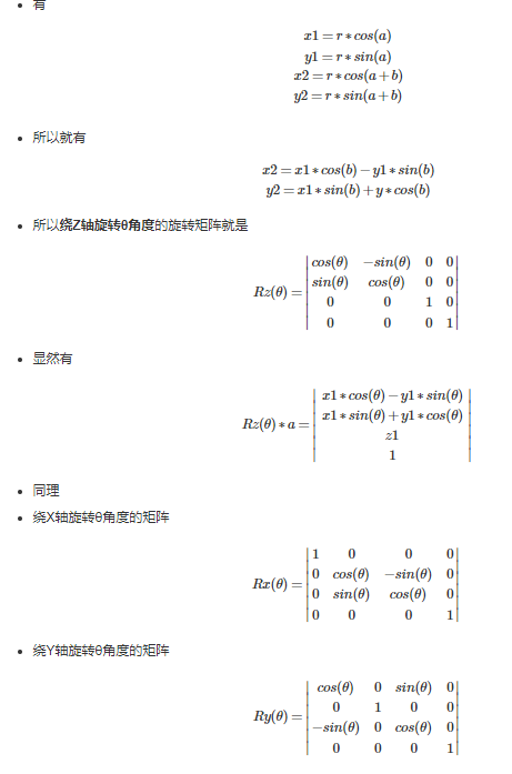
Rotating
First consider the rotation around the Z axis. The forward rotation is when the right thumb is facing the positive Z axis, and the other fingers are facing (counterclockwise)
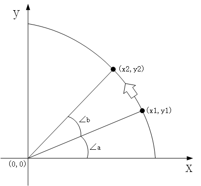
Rotate the Z axis to change the X and Y coordinates
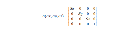
Zooming is based on the original coordinate multiplied by a multiple
Scaling matrix
The view matrix converts the vertices in the world coordinate system with the origin of the world coordinate system to (0,0,0) point to the camera coordinate system with the camera position of (0,0,0).
The true relative position between the vertex and the camera is unchanged, except that the coordinate representation of our original vertex is in the world coordinate system, and what we need is the coordinate representation in the camera coordinate system. So here we just do a coordinate transformation, that is, the coordinates of the same vertex in different coordinate systems are different.
It can be seen from the default camera position that the default camera coordinate system and the world coordinate system are coincident, that is, no conversion is needed. In fact, it is equivalent to the view matrix being the unit matrix.
After changing the position, orientation and forward direction of the camera, the view matrix will really work. The effect of multiplication is to convert the vertices in the world coordinate system to the camera coordinate system.
OnenGL uses gluLookAt function to change camera's external parameters
gluLookAt( Tx, Ty, Tz, Ox, Oy, Oz, Vx, Vy, Vz )
Tx Ty Tz is the location of the camera
Ox Oy Oz is the point where the camera is facing
Vx Vy Vz is the positive direction of the camera
Consider the three vectors of the camera
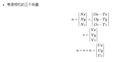
n is the direction vector the camera is facing
v is the camera's positive vector
u is a cross-vector of the two
Requirements: n and v are perpendicular to each other, and nuv is a unit vector (table direction only)
Then you can see the relationship between these three vectors and the camera coordinate system.
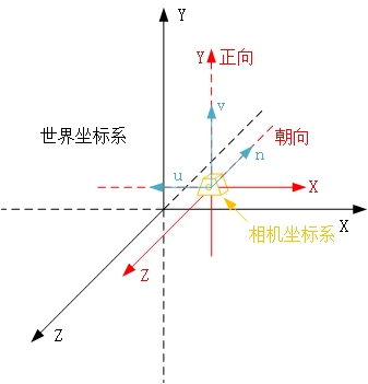
And we also know the location of the camera Tx Ty Tz
For vertices
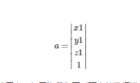
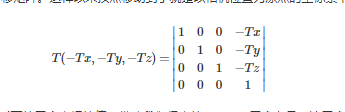
First we move the camera to the origin of the world coordinate system, but because we want to modify the data of the vertex, we multiply the vertex by a translation matrix of T(-Tx, -Ty, -Tz). In this way, the vertex moves to the coordinate system with the camera position as the origin.
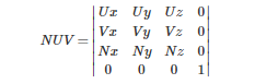
Find the value of the three coordinates of this vertex in the camera coordinate system. With the help of the u, v, n vectors we obtained, these three vectors respectively correspond to the three coordinate axes of the camera coordinate system, so the value of the required coordinate is the vector that takes this vertex as the end point and the camera position as the starting point. The dot product of the three unit vectors of nuv is equivalent to multiplying such a matrix.
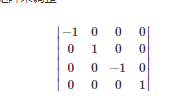
Then we get the value of the coordinates? not yet. Because the positive direction of the vector n and the coordinate axis z are opposite, the positive direction of the vector u and the coordinate axis x is opposite, so we also need to adjust the matrix again to adjust
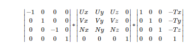
So the final view matrix that we used to convert the world coordinate system to the camera coordinate system is
Projection matrix
The model operation transforms the vertices, which is still in the world coordinate system
View operations convert vertices to camera coordinates
But both of them are transforming vertices, so only one model-view matrix is ​​needed to maintain it.
Then the projection matrix needs another memory space to maintain
Because we have converted the vertices to the camera coordinate system, we set the scene volume to be set with the camera coordinate system.
Only glOrtho's matrix, ie orthogonal projection. Its view is a square area.
glOrtho( left, right, bottom, top, near, far )
Left and right correspond to the two planes x=left and x=right respectively
Bottom and top correspond to the two planes y=bottom and y=top, respectively
Near and far correspond to z=-near and z=-far
This is negative, mainly because the camera's orientation is the negative direction of z. This will cause the viewport to fall in front of the camera.
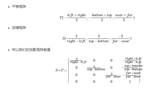
What the projection matrix needs to do is a "standardization."
That is, according to the scope of the scene, the vertices are translated and zoomed so that the original points in the scene all fall within the normalized square with the origin as the center and the side length of two.
The benefit of doing so is the specification, and the subsequent operations of cropping, lighting, etc. are all performed under a unified standard.
Notice that when we zoomed in, we added a minus sign to the z-coordinates. This means that all points in the normalized cube are negative in the z-coordinate.
This means that when we want to “see†the objects in the normalized square, we should look at the origin from the negative infinity of the Z axis, that is, the direction should be the positive direction of Z.
The coordinates of the point obtained in this step, we call it in the clipping coordinate system
12.8V200Ah Lithium Iron Phosphate Battery
Highlights
Saintish lithium iron batteries use top quality cells, which are auto grade A LiFePO4 cells with higher energy density, more stable performance . UL approved for the cells inside the battery.
The lithium-ion batteries are perfect for solar system, caravan, RVs, campers, Yacht, off-grid applications and lead aicd replacement.
Saintish Lithium Iron Phosphate Battery provides 3000+ cycles (@100%DoD) and 10 years lifespan. which is 10 times than lead-acid battery. 1/3 of the weight of lead acid, the LiFePO4 Battery weighs only 23.9kgs each pc, but delivers twice power.
Saintish lithium iron phosphate battery has built-in BMS to protect it from overcharge, over-discharge, over current, and short circuit with excellent self-discharge rate. Operating Temperature: Charge: 0°C~45°C; Discharge: -20°C~60°C.
SPECIFICATIONS
| Rated Capacity | 200Ah | Charge Temperature | 0-45℃ |
| Nominal Voltage | 12.8V | Connection Method | Parallel & Series |
| Energy | 2560Wh | Dimensions | 522*240*218mm |
| Cycle Life | >3000@100% DOD | Weight | 23.9KG |
| Maximum Charging Current | 50A | Terminal Torque | 12-15N.m |
| Maximum Continuous Discharging Current | 100A | Enclosure Protection | IP65 |
| Discharging Voltage Range | 8.4-15.2V | Max. Batteries in Series | 4 |
| Charging Voltage Range | 14.4-15.2V | Certifications | CE, UN38.3, MSDS |
| Discharge Temperature | -20-60℃ | Warranty | 5 Years |
LiFePO4 Battery 200Ah, 200Ah Deep Cycle Battery, 200Ah Battery,Li Ion Battery
Hangzhou Saintish Technology Co.,Ltd. , https://www.saintishtech.com