1 Introduction
With the development of the economy, energy saving and emission reduction and low carbon economy have become the hotspots of global concern. In the field of lighting, LED as the fourth generation of lighting source, stand out with its many advantages such as high efficiency, energy saving and long life. In recent years, LED applications have become more and more popular in the field of road lighting. In streetlight applications, most cities have almost no roads after zero, and it is obviously unnecessary to maintain high brightness on low traffic flows [1]. Therefore, it is especially important to adjust the brightness of street lamps, which is also very important for energy saving and emission reduction.
At present, in the LED street lamp control, timing control is mainly used. In this way, the timer automatic setting and the time-division PWM dimming control are realized for the LED street lamp according to the fixed time set by the timer, which not only saves labor cost but also achieves the purpose of energy saving and emission reduction. The current timer schemes on the market are mixed, and most of them become worse as the usage time increases. Good latitude and longitude timers are expensive and are not suitable for large-scale use on streetlights.
This article designed an LED timer based on the DS1302 and Attiny13 to improve these problems. This paper mainly introduces the hardware and software design of the timer and the hardware and software design of the time programming module for communication with the host computer.
2 overall system composition
The structure of the whole timer system is shown in Figure 1. It mainly includes the upper computer (PC), the real-time clock programming module connected to the PC through the serial port, the timer connected to the programming module through the SPI port, and the LED with PWM dimming driver. Street light.
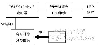
Figure 1 LED street light timing control system structure
The user writes the time to the time programming module by operating the program on the PC interface, and saves it. Then the user operates the time programming module to write the time to the DS1302 in the timer through the SPI interface, thus completing the setting of the timer. In the timer, Attiny13 continuously reads the time of DS1302, timing action, and sends out PWM signal to control LED drive to realize timing control.
This design focuses on the hardware and software design of the timer and time programming module.
3 timer hardware and software design
3.1 Timer hardware design
The timer is mainly composed of a real-time clock part and an MCU circuit. The chip used in the real-time clock part is the DS1302. DS1302 is a high-performance, low-power, low-power real-time clock chip with RAM from DALLAS, which can time the year, month, day, week, hour, minute and second, and can be used for monthly The number of days and the number of days in the leap year are automatically adjusted [2]. The clock can be either a 24-hour clock or a 12-hour clock. The DS1302 consumes very little power and maintains less than 1mW of data and clock information. In the absence of a mains supply, it can operate for up to 10 years with a 3V lithium battery.
The MCU uses the AVR series of 8-bit microcontroller Attiny13. The Attiny13 is a high-performance, low-power 8-bit AVR microprocessor with a simple structure, few pins, and low cost. It is suitable for high-volume use in street lighting control systems to save costs.
As shown in Figure 2, the entire timing module uses 48VDC power supply with the same external LED driver. The voltage regulator circuit composed of Zener diode and capacitor stabilizes the voltage at 4.7V. As the main power supply of DS1302 and the power supply of Attiny13, DS1302 backup power supply. Powered by a 3V lithium coin cell battery.
The real-time clock chip DS1302 provides timing pulses with a 32.768kHz crystal oscillator for time-division and second-second timing. Synchronous communication with the MCU through the SPI three-wire interface is the CE pin, the SCLK serial clock pin, and the I/O serial data pin 3 lines.
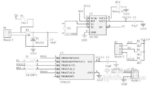
Figure 2 Schematic diagram of the timer circuit
Attiny13 is a timer MCU with its simple function and low price. It uses three IO ports to read the DS1302 time. The internal Tî“”C0 is a general-purpose 8-bit timer/counter module with two independent output compare units and supports PWM function. It provides accurate execution timing and waveform generation, and generates PWM signals on PB0 for dimming [3].
3.2 Timer software design
The software design is mainly written on the Attiny13 microcontroller, written and debugged in the AVRStudio4 environment. The flow chart is shown in Figure 3. The program workflow is as follows:
1) Macro definitions, such as custom timing dimming time and dimming duty cycle;
2) Port initialization, including input and output configuration of IO port, watchdog configuration and timer Timer0 configured as fast PWM mode;
3) For the DS1302 initialization function, define a 1-byte read-write function and a time-division-second read/write function;
4) The main function, cyclically call the DS1302 time reading function to obtain the real-time time on the DS1302, determine whether to switch the lamp, adjust the dimming duty, and realize the timing control.

Figure 3 timer program flow chart
In the program, the user can modify the program according to the actual situation, add different duty cycles and different dimming time nodes, and realize flexible timing control independently.