0 Preface
This article refers to the address: http://
The ISD series voice circuit is a new patented product of the US ISD (InformationStorage Device) company, which breaks the traditional first A/D and then D/A mode, and uses the unique direct storage analog signal technology to greatly increase the storage density. And the analog signal can be saved permanently. The ISD series circuit has established its indisputable position in the field of voice applications due to its natural sound quality, convenient use, single-chip storage, repeated recording and playback, low power consumption, and power-off. Currently, it has been in communication equipment and intelligence. Instruments, security alarms, voice report stations, report quotes, voice explanations, voice recording, voice repeat, teaching instruments, smart toys, electronic gifts and other fields have been widely used.
In this paper, a microcomputer speech board is designed with single chip microcomputer 89C2051 and ISD2560, which realizes segmental recording and combined playback of voice. You can also modify the software to achieve the entire paragraph of admission and loop playback. This product can be used as a subsystem of a voice service system without the need to use a dedicated ISD voice development device.
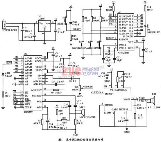
1 ISD2560 voice recording and playback circuit composition
The ISD2500 series of voice chips can be easily interfaced to the CPU via the SPI protocol. This article uses the ISD2560 chip to form a single-chip universal development board using the most commonly used MCS-51 language single-chip 89C51, to combine with the ISD2500 series of voice chips, allowing users to develop a variety of new intelligent digital voice products.
The assembled devices on the development board include:
◇AT89C2051 single-chip microcomputer, the device contains 8031 ​​core, 4 KB program memory that can be repeatedly erased, and 32 I/O ports, and operates with 5 V voltage;
â—‡ISD2560 voice chip, using analog memory technology with excellent sound quality, can be recorded and replayed for 60 seconds;
â—‡LM386 power amplifier with 0.5 W drive capability;
AT24C01 (optional) I2C bus serial memory;
In addition, there are components such as an electret microphone (MIC), a microphone amplifier, a volume potentiometer, and an LED tube. When the board is working, the external power supply voltage of the board is 12 V (regulated), the external speaker is 4 ~ 16 Ω / 0.5 W, the working current is 25 ~ 30 mA during recording, and 50 ~ 80 mA during playback. The quiescent current is 13 mA, and the accompanying software is provided with the demo program function.
2 ISD2560 and microcontroller interface circuit
A0~A9 of ISD2560 are address lines, which have a total of 1024 combined states. The first 600 states are normally used for addressing internal memory, and the last 256 states are used for operating mode. The system is designed to operate directly on the address.
In the interface between the system and the microprocessor, the P/R recording and playback control terminal is in the playback state when the high level is at the high level, and the recording state is at the low level; the P3.5 and P3.7 terminals are used for recording and playback. Stop control, usually used with P/R end; P3.4 end is the end of each piece of information signal output, the signal is a negative direction signal, the time is 12.5ms, and its rising edge flag information ends.
The MIC in the system is the microphone preamplifier input; MIC REF is the microphone compensation end, AGC is the automatic gain control terminal; ANA IN and ANA OUT are the analog signal input and output terminals, and the coupling capacitance between them is usually taken. It is 0.22 to 1 μF.
The voice recording and playback circuit based on ISD2560 in this system is shown as in Fig. 1. Under normal circumstances, the P1 port, P3.4 and P3.5 of the MCU can be connected to the address line of the ISD2560 to set the starting address of the voice segment. P3.0~P3.3 are used to control the recording and playback status. P3.7 is an extended recording button that can be used for recording.
3 system working principle and program design
Although the ISD2560 provides an address input line, the address of its internal information segment cannot be read. Therefore, an operation mode that does not require an address is usually used. However, to read the internal information address of the ISD2560, a dedicated ISD development device is required, and these devices are relatively expensive. To this end, the system uses a microcontroller to control. The method does not need to read the information address, but directly sets the start address of the information segment. There are many ways to implement this idea. The first method is because the address resolution of the ISD2560 is 100ms. Therefore, the internal timer of the MCU can be used for 100 ms, and then the counter is used to count the number of times of the MCU. Thus, the counter value is the address unit occupied by the speech segment. . This method can make full use of the EEPROM inside the ISD2560, so the method can be utilized when there are many fields; if the voice field is small, the second way can be used: that is, the address unit is directly allocated according to the content of each field. Generally, it is calculated by 3 words per 1 s, 180 words can be said for 60 s, and then the address unit required for the speech segment is calculated according to the address resolution of the ISD2560 of 100 ms. This system uses this method.
3.1 AT89C2051 recording and playback control of ISD2560
When recording, first press the record button, the MCU sets the start address of the voice segment through the mouth line, and then makes the PD terminal, P/R terminal and other related ports low to start recording; when the recording ends, the MCU makes these The port returns to high level to complete a voice recording. Then in the same way, you can also take the second paragraph, the third paragraph, and so on. It is worth noting that the recording time generally cannot exceed the preset time of each speech.
During playback, the corresponding voice segment start address can be found according to the voice content to be played, and sent through the interface line. Then set the P/R terminal to the high level, the PD terminal to the low level, and let it generate a negative pulse to start the playback. At this time, the MCU only needs to wait for the information end signal of the ISD2560 (ie, the EOM is generated). Since the signal is a negative pulse and the rising edge of the negative pulse, the segment of speech is played, so the MCU must detect the rising edge to play the second segment. Otherwise, the played speech will be discontinuous, and There will be buzzing, which must be taken into account when programming the software. Figure 2 shows the block diagram of its recording and playback.
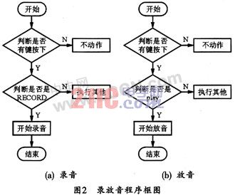
The specific operation method is as follows:
(1) Recording
Insert the jumper on the “REC†side, which is the recording state. Press the “REC†button, the indicator light will be on, and the microphone can be recorded on the board. When the button is released, the recording stops and forms a segment. Press again to record a paragraph. During operation, press the “STOP†button to reset, and when recording again, it will start from the first segment.
(2) playback
Insert the jumper on the “PLAY†side for the playback state. After that, press the “PLAY†button to play a segment. After a period, the playback will stop automatically, and then press “AN†to play the next segment. During the operation, press the “STOP†button to reset, and then play again, starting from the first segment.
3.2 Programming
This program is written with AT89C2051 as the controller of ISD2560 and the crystal frequency is 12 MHz.
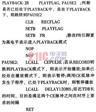
The recording program for taking voice messages and the source program for playing the voice are given below. In fact, playback can also be combined according to the actual situation during playback. The program can also be expanded as needed. Its ISD2560 voice recording and playback system program is as follows:


Thereafter, during recording, the first press of the record button starts recording, and the second press of the record button indicates pause (ie save, set EOM). After pausing the recording, press the playback button to start playback from the address pointer at 0. When recording, the recording can be stopped by the high pulse at the PD (pin P3.1).
When playing, the first press of the play button will start playback. During playback, press the play button again to pause, and press the play button a third time to resume playback at the pause. If you press the record button after the second play button is pressed, you can start recording from the pause. During playback, the high pulse generated by the PD (Pin P3.1) can be used to stop playback and the address pointer is reset to 0. If there is no PD high pulse during playback, it will continue to play until the chip overflow occurs, and then return the address pointer to 0, and start looping.
Here is the recording subroutine:

The system's playback subroutine is as follows:
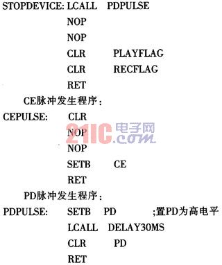
Stop recording or playing the subroutine as follows:
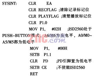
System initialization program:
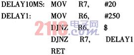
10ms delay program:
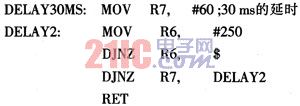
30ms delay program:
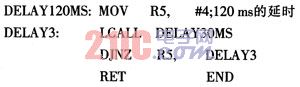
120 ms delay program:
4 Conclusion
The voice recording and playback circuit has the advantages of simple structure, low cost, convenient adjustment and high reliability. Proof of actual use. The system can meet the requirements of normal voice recording and playback. Moreover, it can also be used for other voice recording and playback situations by appropriate adjustment.
Do I need an Aquarium Light timer?
Although it is not necessary,there are unspeakable advantages of an aquarium light timer being used along with bulbs; It helps to simulate the day-night cycle perfectly,timers save energy,when you`re on a vacation it works automatically and gives the light to the plants in your fish tank.
Features
Built-in-Digital-Timer System to control two channels separately
Remote control available
Full Spectrum that mimic natural light to help corals/fish achieve the best balance
90 degree lens thereby to penetrate the depth of water
Easy Adjustable Hanging Kit.
Item Display


Key Features
1.The lifespan is over 50000 hours,low maintenance costs.
2.Energy conservation,saving over 80% energy than the traditional HPS.
3.High light efficiency,90% of the light will be absorbed by the aquatic plants,while just 8%-10% to the HPS.
4.Build-in cooling system,could solve the heat dissipation excellently.
5.Built-in power supply, CE approved, No setup required, just simpler and safer plugs directly into AC85V-264V, no reflector & ballast needed.

Convenient in using lights at the same time.

Package Include
1 X LED Aquarium Light
1 X Free Hanging Kit
1X Free Power Cord


Quality Control systems and after-sales

All the lamps have passed strict quality examination and are packed carefully before shipping.In order that our customers get high quality lamps,we attach importance to every details.
Led Aquarium Light application
1. Indoor use, Compensatory sunlight
2. Sutiable for coral reef, fish and other marine plant growing
3. More better light blue, white, dimmable at different timeDimmable Fish Tank Led Aquarium Lights 40cm

Our Company


Philizon Advantages
Professional: we are professional Led Grow Lights and LED aquarium light manufactuer here in China,you will get Professional and High quality LED Grow Lights and Led Aquarium Light With Timer from us and get good guarantee.
Cost-effective Price:we don`t have the lowest price,but the Led Aquarium Light With Timer you get from us really cost-effective,good quality & decent price.
Win-win situation:Long term business is our mission,we will provide good Led Aquarium Light With Timer and warming service to build a long-term business relationship with you
24/7 unlimted customer service: we are always here for you for your question,any question just email us or call us,we do our best to help you all the way.
Long term warranty: Don`t worry about the quality and we guarantee you 3years warranty for all the LED Plant Grow Light and Coral Reef Led Aquarium Light.
Best buying experience: you will get the tiptop serive you have ever had,just have a try and you`ll see.
Trade Terms
Payment: T/T, L/C, Paypal, 30% deposits before production, 70% balance to be paid before deliverying(Western Union are welcome)
Sample will be delivered within 7 working days.
Discounts are offered based on order quanlityes.
MOQ:sample order are acceptable
Delivery ways:DHL,UPS,FedEx,TNT, door to door,by sea,by air,etc.
Our products ranges:
LED plant grow lights for agricultural lighting;
LED aquarium lights for fish tanks,corals,saltwater tank,marine tank with reef,coral,sps,lps,fish,etc;
Warmly welcome to take a visit on our factory at any time and we will pick you up at the airport in Shenzhen.
Led Aquarium Light With Timer
Aquarium Led Light With Timer,Dimmable Aquarium Led Light,Aquarium Plant Light,Led Light For Aquarium
Shenzhen Phlizon Technology Co.,Ltd. , http://www.philizon.com