The increased number of voltage input rails caused by powering the load points of DSPs, ASICs, FPGAs, and microprocessors makes power supply design more challenging. In particular, infrastructure, industrial and factory automation equipment is more sensitive to noise and other unpredictable events due to increased system power and operating frequency requirements. For example, an erroneous input voltage at system startup can cause system latch-ups, reliability issues, and even system failures.
This article discusses how to configure various voltage output tracking and timing control options for an FPGA or microprocessor to help achieve proper startup and shutdown of a sensitive multi-supply rail system. We will also analyze the ratio and sync trace settings to prevent the FPGA's built-in electrostatic discharge diode (ESD) from being biased or over-pressurized during the rising and falling outputs. These configurations significantly increase system reliability, which is critical to ensure productivity and uptime for a wide range of infrastructure systems and plant floor industrial equipment.
System Configuration
Figure 1 shows a typical application circuit configuration for an FPGA. From the 3.3V highest input rail to the 2.5V second input rail, we found a set of back-to-back ESD diode configurations to act as internal protection circuitry. Another set of back-to-back ESD diode configurations is from the second input rail to the third input rail.
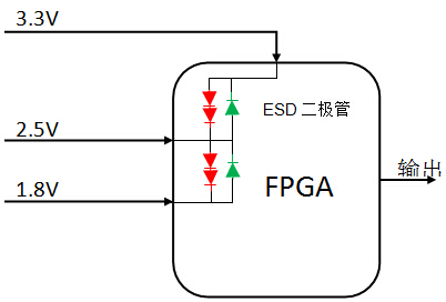
Figure 1. FPGA input block diagram
Let's assume that one of the highest input rails (3.3V in this example) is started first. It then pre-biases the 2.5V output rail to approximately 1.9V and pre-biases the 1.8V rail to 1.2V. Similarly, if the 1.8V rail is first activated, it pre-biases the 2.5V and 3.3V rails. In either case, the ESD diode must be conductive during startup. Figure 2 shows the voltage signal of the 3.3V input rail and its signal sent to the 2.5V rail before startup. The charging current flowing through the ESD diode depends on the startup slew rate, the 2.5V output capacitance, and any load. Performing the same startup scenario with a 1.8V output rail will display a similar voltage signal.
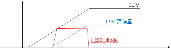
Figure 2. 3.3V and 2.5V pre-biased startup waveforms
Whenever an ESD diode conducts, its reliability decreases. Figure 3 shows what happens to the 3.3V and 2.5V rails when the 2.5V input source is not set to have a pre-bias startup function. As you can see, the FPGA's built-in ESD diode is stressed when the 2.5V rail is activated. Therefore, using a power supply with a pre-biased start function avoids this problem and prevents possible latch-ups in the system. Properly configuring the buck regulator's output voltage tracking ensures that all system power rails are properly soft-started together and prevents the ESD diode from conducting. This simple step improves system reliability and avoids any unexpected system power latching.
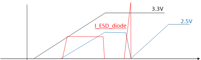
Figure 3. 3.3V and 2.5V startup waveforms
Integrated FET DC/DC converter
Figure 4 shows a typical application circuit for a 2A DC/DC converter with an input voltage range of 2.7V - 5.5V. Only a few peripheral components are used, including the required resistors, capacitors, and inductors. The converter integrates compensation circuitry and power MOSFETs to ensure design reliability, minimum component count and high efficiency up to 95%.
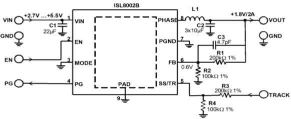
Figure 4. Typical application schematic of the ISL8002B
Pin 5 of the converter provides both soft start (SS) and output tracking (TR) functions. When this pin is tied high, the soft-start time is internally set to 1ms. However, various soft start schemes can be implemented using peripheral components. Figure 5 shows how to program the external soft-start time using the SS/TR function.
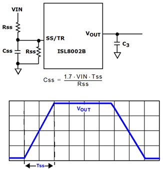
Figure 5. External soft start configuration
The soft start time can be adjusted by setting the soft start resistor RSS and capacitor CSS. The corresponding approximate relationship is shown in Equation 1: 
Formula 1
This soft-start feature can also be configured to track other outputs. Figure 6 shows the ratio tracking configuration for Vout1-Vout2.
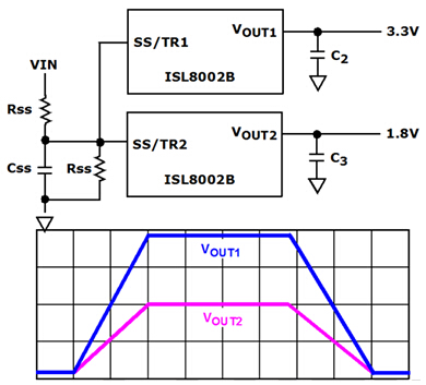
Figure 6. Ratio tracking for Vout1-Vout2
In addition, it is also possible to simultaneously raise the two output voltages by connecting the two SS/TRs together. Similarly, the shutdown function can also perform ratio tracking with each other, just like the soft-start time described in Equation 1.
The synchronization tracking configuration is shown in Figure 7. Simply add a resistor divider at the same ratio as the output voltage sense divider in the feedback loop. In this case, all output voltages rise at the same voltage and slope as the main rail. In general, all other output rails should track the highest voltage rail. Each output will then branch after reaching its stable point. The built-in ESD diode of Figure 1 is protected from conduction or forward bias by providing good control of the start and shutdown of all output rails. Most importantly, this design technique prevents system reliability degradation, latch-up, and worse: system failure.

Figure 7. Synchronous tracking of Vout1 - Vout2
Conclusion
Integrated FET step-down regulators such as the ISL8002B offer a number of easy-to-use solutions for voltage tracking during power-up and power-down. Almost any system voltage tracking requirement can be configured using the circuits discussed in this article. These configurations are not limited to two regulators because they can be used for any number of voltage rails in the system. Ratio tracking is only required by connecting all SS/TR pins together. A resistor divider can also be used to program the system for simultaneous tracking. Both the ratio tracking and the synchronous tracking method prevent the ESD diode from being subjected to unnecessary stress, thereby improving the overall reliability of the system.
About the Author
Tu Bui is the application engineering manager for industrial and infrastructure products at Intersil. He is responsible for switching regulator product development and all related customer application support. Prior to joining Intersil, Mr. Bui was a member of AT&T Bell Laboratories' Technical Staff Design Engineer, where he developed and launched more than 20 world-class products and product families. Mr. Bui holds a BS in Electrical Engineering from the University of Arizona and a Masters in Engineering Management from Southern Methodist University.
Amusement Park Rides Light
· Ferris Wheel, Merry-Go-Round, Pirate Ship, Pendulum, Bumper Car, Rotor and so on.
Stage Decoration Light
· KTV, Disco, Bar, Night Club and other stage light.
Commercial Light
· Hotel, Shopping Mall, Theater, Square and so on.
Kids Ride Decoration
· Castles, Robot, Mini Carousels, Car, Train and etc.
Our other products range:Led underground Light, LED Underwater Light, LED Wall Washer Light, LED Linear Light , LED Outdoor Flood Light, LED Garden Light , LED Landscape Light , LED Strip Light , LED Step Light etc.
LED Point Light
RGB LED Point Source,Building Decoration Start Light,LED Outdoor Point Light,Star LED Point Source
SHENGYA LIGHTING TECHNOLOGY CO., LTD. , https://www.syalighting.com