The data packets flowing in UFS are called UPIU (UFS Protocol Information Unit). It is a fixed-format data structure used to transmit commands or requests sent from the application layer, as well as data or status information related to them. It is FIS in SATA, TLP in PCIe. Let's look at how commands or requests are executed in UFS.
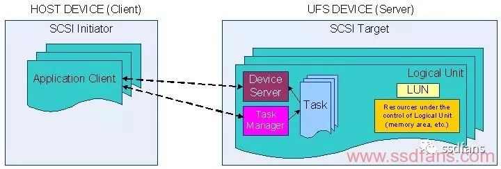
UFS uses the "client-server" or master-slave command architecture. The UFS host (client, command initiator, and Initiator, they both mean the same thing) sends a command or request to a UFS device (server, Target), then UFS. The device executes the command and returns the command status (Response).
The execution of a command or request consists of the following stages:

Command phase: The host initiates a command or request to the device, which is "cause";
Data stage: The transmission of data related to the command, such as read and write commands, involves the transmission of data; some commands do not involve the transmission of data, so this stage does not always exist, related to specific commands and requests.
State stage: After the device executes the command, it must return the command execution status information to the host. This is "fruitful" and essential. In PCIe, there are Posted and Non-posted TLPs. For the former, the command executor does not need to return the command execution state to the command originator. For the latter, the command executor must return the state to the command originator. For UFS, its commands are always non-posted, that is, the device must return the command state to the host.
During the execution of the command, regardless of the stage, the UFS host and the device exchange information through the UPIU.
1. The UFS host sends a command to the device by issuing a command or requesting UPIU.
2. UFS host or device transmits data through UPIU.
3. The UFS device returns command status information to the host through UPIU.
Let's take a look at what UPIUs are in UFS.
Command or request UPIU
The previous chapter saw that the application layer includes three modules: UFS commands, device managers, and task managers. The transport layer generates different types of UPIUs according to the commands or requests sent by different modules.
The UFS command module sends a simplified version of the SCSI command. When the transport layer receives the command request, it generates: COMMAND UPIU to encapsulate the command.
The application layer manages task queues through the task manager, such as commands in Abort and query command queues. When the transport layer receives a request from the task manager, it generates: TASK MANAGEMENT REQUEST UPIU, encapsulating the request.
UFS manages UFS devices through the device manager, such as setting and querying the configuration of UFS devices. When the transport layer receives a request from the device manager, it generates: QUERY REQUEST UPIU, encapsulating the request.

Data transmission related to UPIU
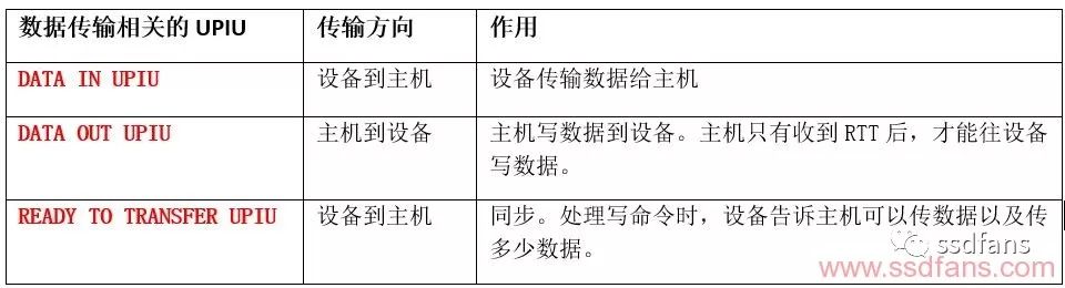
After the host sends a similar read command to the device, the device needs to return data to the host. The device transmits data to the host through DATA IN UPIU.
After the host sends a write command similar to the device, the host needs to write data to the device. The host transfers data to the device through DATA OUT UPIU.
UFS host is a warm man, when it writes data to the device, it will consider whether the device can receive data at this time (because the device may not have enough space to receive host data at this time), after it sends a write command to the device, The data will not be transmitted to the device immediately, but the device will be notified there. When the device is ready to receive data, and how much data is received, the device informs the host through READY TO TRANSFER UPIU (RTT). When the host receives the RTT, it starts to transmit data according to the RTT information. As for the amount of data transmitted each time, this information is included in the RTT and the host transmits according to the RTT.
Therefore, the host can send DATA OUT UPIU only after receiving the RTT of the device!
Note that read commands do not require this mechanism. Because the device obtains data from the flash memory, it is the device control data transmission. For the host, it has enough space to receive data before the read command, so there is no case where the host has no space to receive data.
State UPIU
As you can see from the above, the host has three kinds of requests: SCSI command, Task Management Request issued by the task manager, and Query request issued by the device manager. For different commands or requests, the device returns the corresponding state UPIU to the host after executing the corresponding task.

Other UPIU
In addition to the above conventional UPIU, there are other UPIUs for other uses.
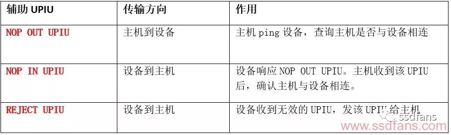
After the device is powered on, the host detects whether it is connected to it and sends a NOP OUT UPIU to the device. We usually want to see if we can connect to a computer or website and send a ping command. NOP OUT UPIU is similar to the ping command.
When the device receives NOP OUT UPIU, it returns NOP IN UPIU. After receiving the UPIU, the host confirms the connection with the device and can then perform subsequent operations.
The last UPIU is REJECT UPIU. When the device receives an invalid UPIU, it sends REJECT UPIU to reject the invalid UPIU.
UPIU summary

Stealing lazy, I will directly paste this UFS spec here. Counted, a total of 12 UPIUs. After my previous explanation, the reader should now understand the role of each UPIU.
UPIU interaction example in read and write commands
In the foregoing, we are all looking at UPIU individually. Now we take the read and write commands as examples to see how they are combined to complete the command processing.
The first is an example of "host reads 96 KB of data from the device."

First, the host sends a command to read the 96 KB data to the device. Then the device executes the command, returns the data in three batches to the host, and finally returns the command execution status to the host.
Then there is an example of "Host writes 64 KB of data to the device."
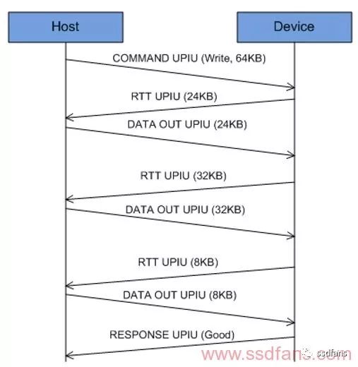
The host sends a command to write 64 KB of data to the device, where it waits for the device to respond. Soon, the device says that you can transfer 24KB of data down, so the host writes 24KB of data to the device; then, the device again informs you that 32KB of data can be transferred and the host does. Finally, the device informs us that the last 8 KB of data can be transmitted, and the host then writes the last 8 KB of data. Finally, the host receives a response to the completion of the device command execution.
We see that the host must wait for RTT to start data transfer!
Tower Battery Cabinets,Anderson Terminals,Battery Breaker,Tower Battery Package
Shenzhen Unitronic Power System Co., Ltd , https://www.unitronicpower.com