0 Preface
In recent years, due to the increasingly obvious trend of integration of consumer electronics, computer and communication (3C), embedded systems have once again become a hot spot of research and application. The embedded operating system (Real-TIme Embedded OperaTIngSystem, RTOS or EOS) is a real-time operating system software that supports embedded system applications. It is an extremely important part of embedded systems (including hardware and software systems), usually including Hardware-related underlying driver software, system kernel, device driver interface, communication protocol, graphical interface, standardized browser Browser, etc. The Windows CE operating system is a multi-threaded, full-priority, multi-tasking operating system designed by Microsoft for the limited resource platform as a whole. Win CE supports a variety of processor product families, including x86, Xscale, ARM, MIPS and SH series. Its modular design allows it to customize the user electronics from the handheld to the dedicated industrial controller, and the choice of system modules and components determines the amount of memory required.
The Windows CE operating system can support a variety of hardware devices because each hardware device has its own device driver, otherwise the hardware will not work under Windows CE. Win CE provides four device models, two of which are dedicated to Win CE models, and two of which are from other operating systems. Two models based on Win CE are native device drivers and stream interface drivers; two external models are used for Universal Serial Bus (USB) and Network Drive Interface Standard (NDIS) drivers. The following is a flow interface driver design for the CAN bus controller SJA1000 based on Samsung's ARM9 core chip S3C2410 under Win CE system.
1 CAN bus and controller working principle
The controller area network CAN is a serial communication bus defined by ISO and is mainly used for various process detection and control. It is a multi-master bus and the communication medium can be twisted pair, coaxial cable or optical fiber. Communication rates up to 1 Mb/s. The CAN bus communication interface integrates the physical layer and data link layer functions of the CAN protocol, and can complete the framing processing of communication data, including bit filling, data block coding, cyclic redundancy check, and priority discrimination. Its basic design specifications require high bit rates and high immunity to electromagnetic interference, and can detect any errors that occur. Due to these characteristics of the CAN serial communication bus, it is naturally widely used in the automotive industry and the aviation industry.
The SJA1000 is a stand-alone controller for mobile network and regional network control (CAN) in general industrial environments. It is an alternative to the Philips Semiconductors PCA82C200 CAN controller (BasicCAN). And it adds a new working mode (PeliCAN) that supports the CAN2.0B protocol with many new features. Its internal architecture is shown in Figure 1.
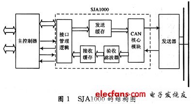
The CAN core module controls the transmission and reception of CAN frames. The interface management logic is responsible for connecting to an external host controller, which may be a satellite control device or any other device. The SJA1000 multiplexed address/data bus access registers and control read/write strobe signals are processed here. The SJA1000's transmit buffer is capable of storing a complete message (extended or standard). When the primary controller initiates transmission, the interface management logic causes the CAN core module to read the CAN message from the transmit buffer. When a message is received, the CAN core module converts the serial bit stream into parallel data for the acceptance filter. With this programmable filter, the SJA1000 can determine which messages the host controller will receive. All received messages are accepted by the acceptance filter and stored in the receive FIFO. The number of stored messages is determined by the working mode and can store up to 32 messages.
2 stream interface driver working mechanism
Compared to native device drivers, the stream interface driver behaves as a dynamic link library that is uniformly loaded, managed, and unloaded by the device manager. Compared to internal device drivers with separate purposes, all stream interface drivers use the same set of interfaces and call the same set of functions - the stream interface function. Win CE's file system communicates with the stream interface driver through these population point functions, thereby achieving the purpose of the application accessing the driver and operating the hardware. The DLL interface to be implemented by the stream interface driver is shown in Table 1.
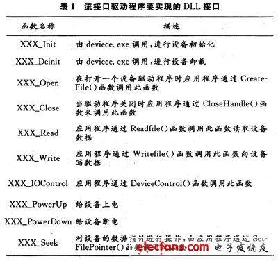
In actual development, the three letters of XXX in the above interface name are replaced by the device file name of the specific device. After the stream interface driver is compiled, a DLL file is generated, that is, a dynamic link library file.
Bluetooth speaker,Portable bluetooth speaker, wireless protable outdoor speaker
SHENZHEN YINZHIGUAN DIGITAL TECHNOLOGY CO.,LTD , http://www.yzgmusiccrown.com