Any information needs to be transmitted with the help of sound, light, and electrical signals. Because the attenuation of light and electrical signals in seawater is relatively serious, and sound waves are the only energy situation known to humans that can travel long distances in water. Therefore, near Over the years, the research and development of underwater acoustic communication systems in the ocean has become a hot spot. Hydroacoustic communication refers to the communication system that uses the hydroacoustic channel to transmit data between the two parties. The structure of the hydroacoustic communication system is very similar to the structure of the traditional radio communication system, but the hydroacoustic communication system converts electrical signals into acoustic signals. , The acoustic signal carrying information is transmitted in the water to complete the data transmission of the system.
1 The overall structure of the underwater acoustic communication system
The design block diagram of the underwater acoustic communication modulation/demodulation system based on CDMA is shown in Figure 1. The whole design system mainly realizes the CDMA modulation/demodulation of the signal, controlling the DAC and ADC for digital acquisition, and the analog-to-digital conversion and digital-to-analog conversion are performed by Dedicated integrated chip to achieve. The function of the power amplifier is to amplify the modulation signal. Signal amplification and conditioning are the inverse process of power amplification; the transmitting underwater acoustic transducer realizes the conversion of electromagnetic energy generated by the amplifier into acoustic energy, and the receiving underwater acoustic transducer transforms the electromagnetic energy generated by the amplifier into acoustic energy. The received acoustic signal is converted into an electrical signal.
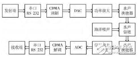
Figure 1 Basic model of underwater acoustic communication system
The circuit block diagram of the designed underwater acoustic communication system is shown in Figure 2. The main control chip of the system is the EP3C10E144C8N of Altera's Cyclone â…¢ series, which mainly includes communication module, spread spectrum module, BPSK modulation module and corresponding demodulation module; the peripheral circuit includes the power supply circuit of the whole system, and realizes the A/D conversion. ADS7800 chip, TY5639 chip that realizes D/A conversion, crystal oscillator circuit that provides clock signal for the entire system, level conversion chip 74HC245A that realizes TTL level and CMOS level compatibility, JTAG interface for programming the target program, and It also includes circuits for data transmission.
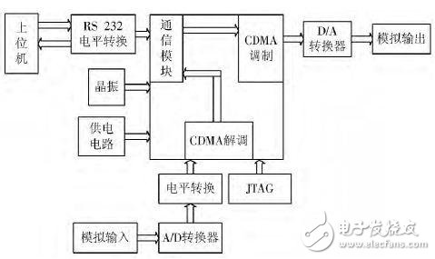
Figure 2 Block diagram of the circuit design of the underwater acoustic communication system
The working process of the system: First, the host computer simulates the transmitter. The digital signal to be sent is sent to the FPGA chip through the serial port. The communication module receives the digital information and then transmits it to the spread spectrum module BPSK modulation module. So far, the received digital signal The signal generated after the information is modulated is converted into an analog electric signal by the D/A converter, and then the electric signal is converted into an acoustic signal by the underwater acoustic transducer and sent out, and the acoustic signal carrying the information sent by the sender is carried in the underwater environment To spread. The second is the receiving end. The receiving end also has an underwater acoustic transducer responsible for converting the received acoustic signal into an electrical signal. After the A/D converter, the obtained data signal is synchronized and then demodulated by BPSK, and finally demodulated The digital signal is transmitted to the serial port through the communication module, and then sent to the receiving end, and the underwater acoustic communication process is completed.
2 FPGA implementation of the system
CDMA, also known as code division multiple access, is a modulation and multiple access method based on spread spectrum communication. Spread spectrum communication technology is a method of information transmission. The frequency bandwidth occupied by the signal is required to be far greater than that necessary for the transmitted information. Minimum bandwidth; the expansion of the frequency band is achieved through coding and modulation methods, and has nothing to do with the transmitted information data; at the receiving end, the same spreading code is used for relative demodulation to despread and restore the transmitted information data. The theoretical basis is the Shannon formula in information theory:
C = B log2 (1 + S/N) (1)
In the formula: C is the maximum information rate that the channel may transmit, representing the channel capacity; B is the channel bandwidth; S is the average power of the signal; N is the noise power.
It can be seen from the formula (1) that when the signal-to-noise ratio is small, the method of increasing the bandwidth can be used to improve the anti-interference performance of the system to ensure that the channel capacity remains unchanged. In other words, under the same channel capacity, the broadband system has better anti-interference performance than the narrowband system. Therefore, when the signal-to-noise ratio is too small and the communication quality cannot be guaranteed, the method of increasing the bandwidth can be used to improve the communication quality.
Figure 3 and Figure 4 are the working principle diagrams of the direct-spread system. The information code output by the signal source and the pseudo-random code generated by the pseudo-random code generator are modulo 2 added or multiplied to generate a rate equal to the pseudo-random code rate. Spread-spectrum sequence, and then use carrier to modulate the spread-spectrum sequence to obtain the spread-spectrum modulated radio frequency signal. The despreading process at the receiving end is the same as the spreading process, and the received signal is demodulated after relevant despreading with a local pseudo-random sequence.
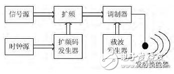
Figure 3 Schematic diagram of transmitting unit
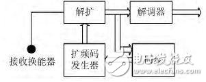
Figure 4 Schematic diagram of the receiving unit
2.1 Launch unit design
The transmitting unit mainly includes a pseudo-random sequence code module (PN code generator), a spread spectrum module, and a BPSK modulation module.
2.1.1 PN code generator
The PN code generator adopts the principle of the m sequence generator, and the m sequence type longest linear shift register is formed by the shift register plus feedback. The necessary and sufficient condition for a linear feedback shift register to generate m-sequences is: the period characteristic polynomial is the primitive polynomial. In this design, a 7-stage generator with a period of 127 is designed. The primitive polynomial selected is f (x) = 1 + x + x2 + x6, which is written in VHDL language.
2.1.2 Spread Spectrum Module
The m sequence generated by the PN code generator is XORed with the input digital signal to complete the spread spectrum function. The RTL diagram of the spread spectrum module is shown in Figure 5.
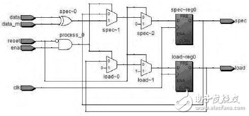
Figure 5 RTL diagram of spread spectrum module
2.1.3 BPSK modulation module
The modulation module selects the BPSK modulation with constant envelope characteristics, which is a modulation method in which the phase of the carrier is controlled by the baseband signal to make the phase of the carrier jump. When the symbol is '1', the modulated phase becomes 180°. When the symbol is '0', the modulated phase becomes 0°. For this reason, the BPSK modulation module is designed, and the design instantiates two ROMs. , Generated by Matlab. The mif file is used to store the data of 0° and 180°, in addition to the address selector and the data selector.
The simulation diagram of the entire transmitter is shown in Figure 6, clk is the system clock, clk_bpsk is the clock for BPSK modulation, datain is the input data, m_out is the generated m sequence, spre_out is the waveform after spreading, and bpsk_out is the BPSK modulation. Output. It can be clearly seen from the result that the output signal has two phase changes, one is a jump from 0°~180°, and the other is a jump from 180°~0°. It can be seen that the data is correctly modulated.
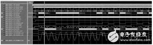
Figure 6 Simulation diagram of transmitting unit
2.2 Design of receiving unit
In order to verify the feasibility of the designed system, a BPSK demodulation and despreading module is designed in the system, and the modulated data at the transmitting end is directly used as the input data of the receiving end. A ROM is also instantiated in the BPSK demodulation module, which stores data with a phase of 0°, multiplies the data synchronized by the carrier with the output data of the ROM, and then performs a sampling decision. The decision result is shown in Figure 7. In the figure, spre_out is the data spread at the transmitting end. sam_out is the sampling decision and delayed by 70 clk_bpsk. The purpose is to keep the data exactly on the rising edge of the data. p_out indicates the start of demodulation output. From the figure It can be seen that the data after the decision delay is exactly the same as the data after the spread spectrum, but the delay for a period of time indicates the demodulation time.
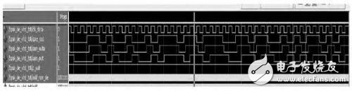
Figure 7 BPSK demodulation module result diagram
Assuming that the PN code has been synchronized in the despreading module, here is only a certain time delay to make it exactly the same as the PN code at the transmitting end, and then perform XOR with the BPSK demodulated data to obtain the output data. As shown in 8, sp_end is the despreading data, p_end is the flag bit to indicate the start of despreading, and datain is the original input data. It can be seen from the figure that the original input data of the despreading data field is the same, but there is After a period of time delay, it can be seen that the system has carried out correct demodulation.
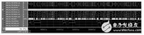
Figure 8 Demodulation simulation diagram
3 Conclusion
In this paper, an underwater acoustic communication modulation/demodulation system based on FPGA-based direct sequence spread spectrum system is designed. The purpose is to make the underwater acoustic wireless communication have stronger anti-interference and confidentiality. The system includes signal spread spectrum and BPSK modulation and corresponding demodulation module, and successfully verified on Modelsim simulation software. Although BPSK modulation is compared with 2FSK, 2ASK has the advantages of narrow bandwidth, high frequency, and strong anti-interference, and it is widely used in medium and high-speed communications. But in higher-speed communication systems, BPSK modulation can no longer meet the requirements of frequency band utilization and system effectiveness, so a multi-band phase modulation system is basically adopted. In addition, the absolute phase modulation system will produce phase inversion, so the relative phase phase modulation system should be considered. The underwater acoustic wireless communication based on this idea will definitely have better application prospects.
ZGAR GenkiIppai Pods 5.0
ZGAR electronic cigarette uses high-tech R&D, food grade disposable pod device and high-quality raw material. All package designs are Original IP. Our designer team is from Hong Kong. We have very high requirements for product quality, flavors taste and packaging design. The E-liquid is imported, materials are food grade, and assembly plant is medical-grade dust-free workshops.
From production to packaging, the whole system of tracking, efficient and orderly process, achieving daily efficient output. WEIKA pays attention to the details of each process control. The first class dust-free production workshop has passed the GMP food and drug production standard certification, ensuring quality and safety. We choose the products with a traceability system, which can not only effectively track and trace all kinds of data, but also ensure good product quality.
We offer best price, high quality Pods, Pods Touch Screen, Empty Pod System, Pod Vape, Disposable Pod device, E-cigar, Vape Pods to all over the world.
Much Better Vaping Experience!


Pods, Vape Pods, Empty Pod System Vape,Disposable Pod Vape Systems, Japanese culture style
ZGAR INTERNATIONAL(HK)CO., LIMITED , https://www.zgarette.com