USB type-c offers many features, including advanced flexibility and convenience for end users. System designers must carefully choose the options offered so that the overall system cost can be controlled to a reasonable extent. There are two choices that have the greatest impact on the cost and complexity of the system. One is the inherent power of type-c at 15W, and the other is enhanced power and video support. This article discusses how to implement a USB type-c port and minimize its impact on existing systems.
Introduction
In the electronics industry, USB type-c exists in the minds of every system designer. This interface combines data, power, and video into a single connector interface. It gives designers a real chance of not using a cylindrical power jack connector in a brand new platform. USB Type-C supports USB 2.0 and USB 3.1 and offers alternate (Alt) mode options, such as DisplayPort for video. The USB Type-C introduces an inherent power supply of 15W and an enhanced power supply of up to 100W when adding USB power transfer (USB PD). This interface introduces a smaller, thinner, and more robust socket that can support data rates up to 20Gbps. This cable supports two-way and two-sided flipping, and can be connected to one host or one client device in either direction. System designers are thinking about how to provide these desirable features and flexibility to users.
Let's first imagine that designers are designing a new notebook platform. If you include the USB Type-C port, how much will the overall cost increase? How many new Type-C jacks do you need? Are they all full-featured sockets? The flexibility and ease of use that USB Type-C provides to end users also increases the complexity and cost of system implementation. While new ecosystems offer more options for implementation, system designers must be cautious when trying to use this technology to keep their overall costs within acceptable limits.
So what does the new notebook platform look like? Some system designers will likely choose to include only one full-featured Type-C port and provide enhanced power capability with USB-PD. This super port will support Alt mode video. In order to save costs and reduce complexity, a designer may want to use other ports to provide simplified features, such as the 15W inherent Type-C power supply, and USB data support.
A major consideration is to replace the previous USB port with a USB Type-C while minimizing the impact on existing platforms. This article outlines how to convert a USB 3.0 legacy port to a USB 3.1 Type-C port with minimal changes.
Type-C USB 3.1 implementation
The USB Type-C is the same connector on both ends - the same socket on the host and client devices, the same plug on both ends of the cable. Figure 1 shows a USB Type-C socket pin diagram. It should be noted that the 24-pin interface uses a symmetrical arrangement, which makes cable flipping more convenient.
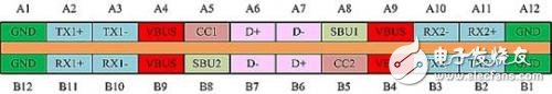
Figure 1: USB Type-C Socket Pin Diagram (front view) Source: Type-C Specifications
In addition to USB 3.1 TX, RX, and USB 2.0 D+, D-signal, 2 CC pins are used for channel configuration (CC) and USB-PD communication. A typical system implementation is to short the two D+ signals and two D-signals with a stub connection, which eliminates the need for a USB 2.0 multiplexer (mux) to accommodate plug flipping. However, due to concerns about signal integrity, a 2:1 multiplexer is required on each side of the Type-C interface, so that stub connections for USB 3.1 signals are not feasible. If you use Alt mode, you need a USB-PD function, and the multiplexing configuration becomes more complicated.
A typical USB 3.1 implementation consists of two basic functions: a CC controller that manages the link; and a USB 3.1 multiplexer for RX and TX signals that selects the connected end based on the Type-C plug direction. The CC controller needs to be able to configure itself as a downstream port (DFP), uplink port (UFP) or dual purpose port (DRP) depending on the desired system operation. Table 1 summarizes the data/power operation modes for different applications.
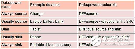
Figure 1: Device Data/Power Category for USB Type-C Applications
USB Type-C host-client implementation
The USB Type-C includes a channel configuration feature; this feature creates a USB link between DFP and UFP. In a traditional USB port definition, one DFP port can be considered a host, and UFP can be considered a device. The CC function is used to determine the following:
DFP to UFP connection/disconnection detection and plug orientation
DFP to UFP (host to device) and power supply relationship (power supply / power consumption) detection - in the absence of USB-PD by default, DFP (source) power supply, UFP (charge) power consumption
USB Type-C VBUS current notification made by the power supply side, the power consumption side detects
Once connected, power and data transfer purposes can only be changed via USB-PD
Even if a socket has 2 CC pins, CC1 and CC2, only a single CC wire is connected in one cable. For each CC pin, the DFP has a pull-up voltage and the UFP has a pull-down voltage. Monitoring the nominal voltage on the CC pin provides direction and connection detection.
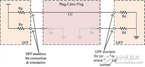
Figure 2: Channel configuration pull-up/pull-down model
A DFP uses different resistor pull-up (or current source) values ​​to inform its current supply. Alternatively, a UFP can detect its power consumption by using a pull-down resistor and performing a voltage comparison. In the absence of a USB-PD, three power settings are possible - the previous default (900 mA for USB 3.1, 500 mA for USB 2.0), 5 V on VBUS, 1.5 A and 3 A current.
Figure 3 shows a typical host-client (DFP/UFP) implementation of USB Type-C. An example of a USB 3.1 host is a desktop or laptop. The Type-C port in the PC is similar to DFP and runs as a USB host to power the client device. On the other hand, a typical example of a USB SuperSpeed ​​client device is a portable hard disk. This hard drive runs as a USB device and is powered by VBUS.
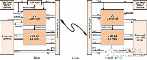
Figure 3: Typical Host-Client (DFP-UFP) implementation of USB Type-C
According to the Type-C specification, the client/user is responsible for managing power consumption. Therefore, a client device needs to dynamically control power consumption based on the host's current notification. An alternative method is to keep the flow consumption within the default limits. It is also possible for DFP to implement current limiting for accessory system protection.
If a DFP supports USB 3.1, it needs to provide 5V power to the active electronics in VCONN within the USB Type-C cable. VCONN is applied through the CC pin (CC1 or CC2) of the socket; the socket is not connected through the CC wire inside the cable. Instead, it powers the circuit at the near end of the plug. It is important to note that each full-featured Type-C cable requires an electronic tag. In addition, longer cables may require an active signal conditioner.
USB Type-C dual-purpose port implementation
USB Type-C also defines a DRP; it alternately identifies itself as DFP or UFP before a stable connection state is established. If a DRP is paired with a DFP or UFP, it runs as a DFP or UFP, respectively. If 2 DRPs are paired, the results are random but subject to 2 optional features: Try.SRC and Try.SNK. A DRP with Try.SRC is more likely to become a DFP (source) if the other end has no preference, and a DRP with Try.SNK is more likely to become a UFP. These characteristics are important for achieving an orderly power/power relationship in an ecosystem. For example, laptops should power their phones—even if they both have DRP capabilities.
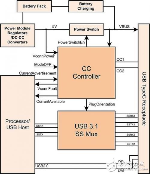
Figure 4: Typical DRP implementation of USB Type-C
Type-C USB 3.1 solution
To easily convert an existing USB platform (including legacy sockets) to a USB Type-C without major system redesign, a CC controller device is required. In order to support USB SuperSpeed, an additional device with USB SuperSpeed ​​multiplexing is also required.
The TUSB321 is a single-chip USB Type-C port CC controller that can be configured as a DFP, UFP or DRP. It is an autonomous device. In fact, with some pre-configured configuration, it does not require any user intervention. However, software intervention is optional, which provides some additional functionality that is useful to the designer.
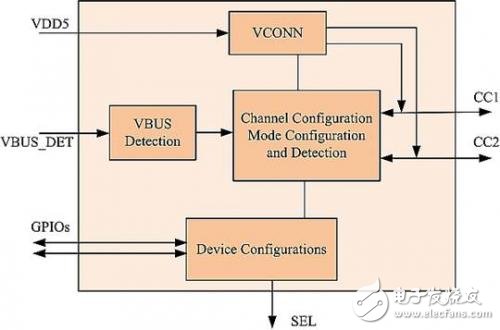
Figure 5: Functional block diagram of a typical channel configuration device
The HD3SS3212 is a USB SuperSpeed ​​passive multiplexer; it uses the Signal Engineering Laboratory (SEL) signal provided by the CC controller to select the active USB 3.1 signal to accommodate Type-C flip plugs; for data rates up to 10 Gbps, This plug supports USB 3.1 Gen 1 and Gen 2.
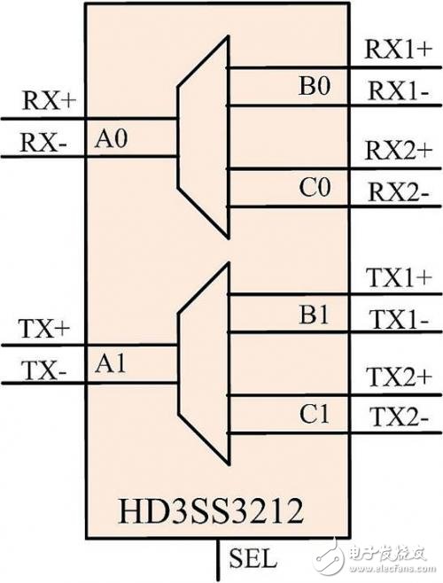
Figure 6: Example of multiplexer operation selected for SS RX/TX pair
Some systems may require enhanced signals for USB SuperSpeed ​​to meet the socket requirements. A transponder-driven multiplexer provides dual functions of signal conditioning and USB SuperSpeed ​​switches. The USB Type-C provides an audio accessory feature; this feature provides headphone and microphone functionality through the Type-C jack, eliminating the need for a 3.5mm audio port in some systems. The audio signal uses D+, D- and USB signals. To provide audio functionality, an additional multiplexer will be required, which is beyond the scope of this article.
to sum up
Due to its functionality and flexibility, USB Type-C will be widely welcomed by electronics enthusiasts. System development and component costs are not significantly increased by the existence of this huge advantage. For most basic implementations, such as USB and 15W, this conversion is easy - you only need to upgrade the socket, add a CC controller, and an optional USB 3.1 SS multiplexer.
Solar System Batteries,60Ah Ni-Fe Battery,24V Nickel Iron Battery Bank 60Ah,Ni-Fe Battery 10~80Ah
Henan Xintaihang Power Source Co.,Ltd , https://www.taihangbattery.com